
This article highlights the benefits of the next ShaftDesigner major update with a brand-new Graphical User’s Interface (GUI). ShaftDesigner 1.10 family main differences compared to the previous version and new features are demonstrated. Video related to this topic is also available in the end of this article.
Contents:
For the last 30 years, Intellectual Maritime Technologies have been supplying engineers around the world with high-quality software for marine propulsion shafting alignment and vibration calculations. This time we release the significant update of ShaftDesigner to the 1.10 version. This several years work has resulted in the User’s Interface update as well as the new unique features added. This is a step forward to provide a comfortable working environment for the user and increase productivity.
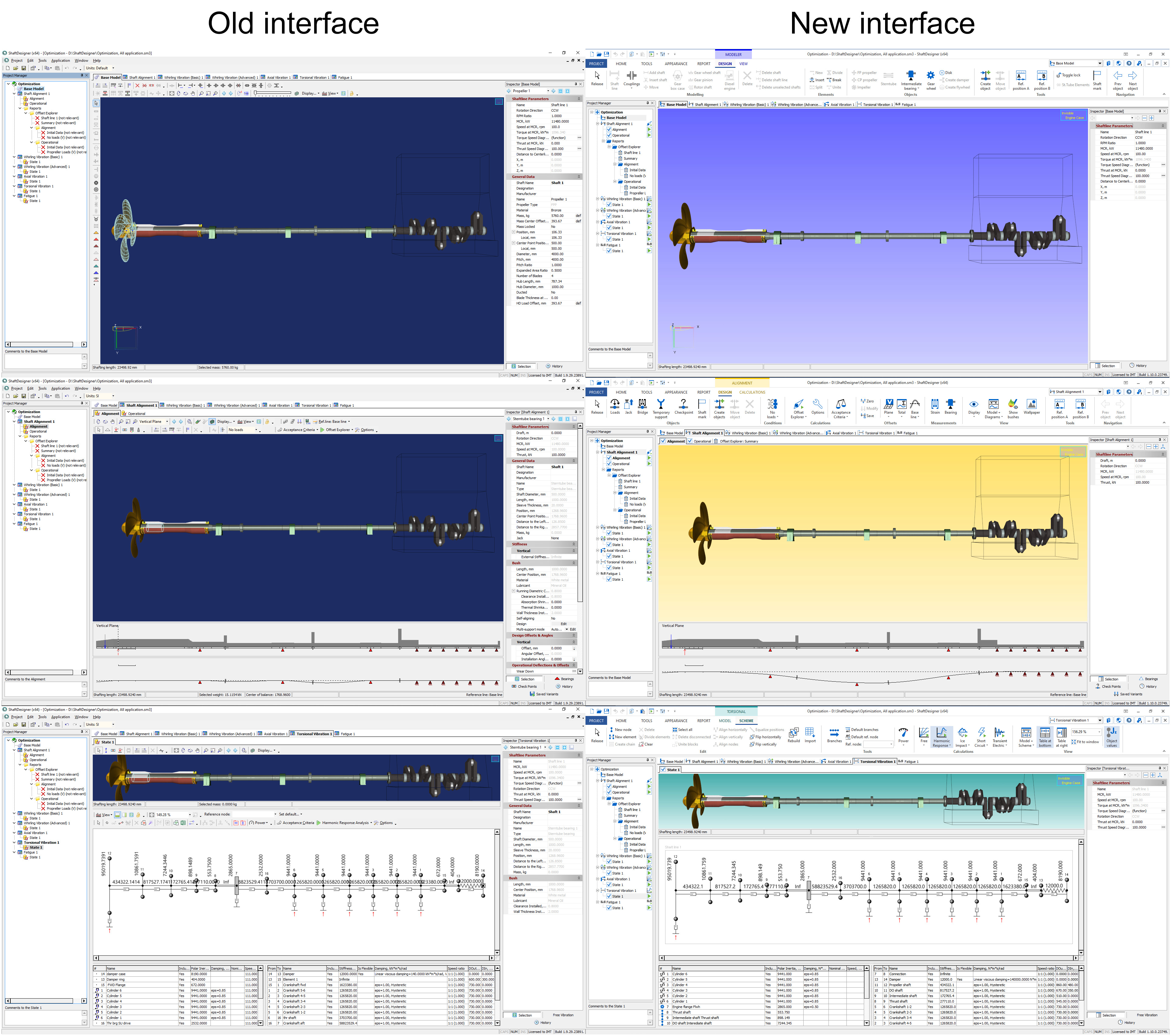
The new interface is based on the ribbon concept, similarly to the modern office and engineering software GUIs. The ribbon at the top groups the buttons and controls conveniently for the user. The new interface contains all the features familiar to experienced users of ShaftDesigner. The beginners will speed up the learning process because now it becomes much easier to find the necessary features.
Let’s have a look at the main differences in the User’s Interface. The look and feel of the graphical user’s interface were redesigned significantly, however the main idea of the software is still the same. Specifically, ribbon toolbars, gradient background, more relevant modern icons’ style.
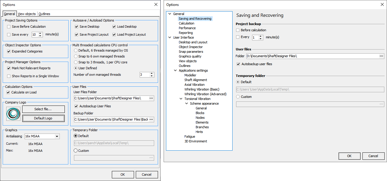
2.1. Program Options Window
Some windows are completely reworked. For example, program settings allow more convenient and structured customization of the user interface and workflow.
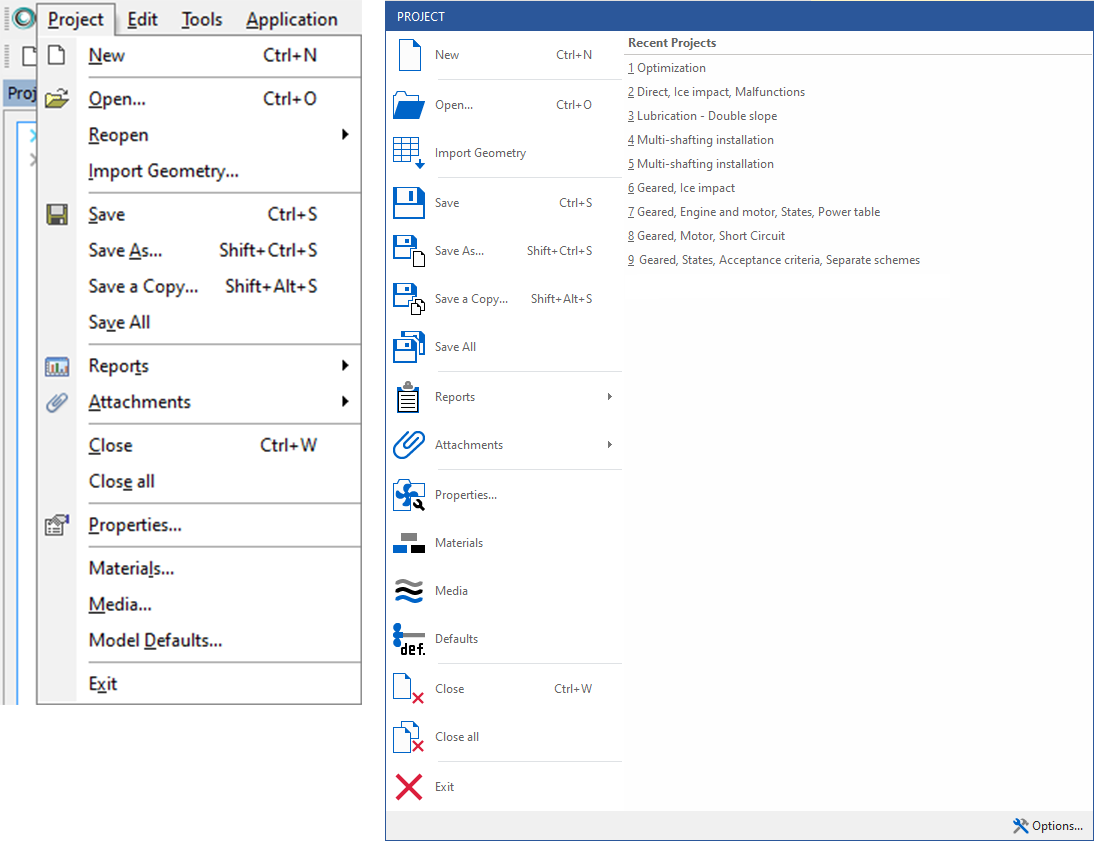
2.2. Project Menu
The Project menu was redesigned. In this menu, you can create a project, open, and save projects in different ways, close current or all projects, set up properties, materials, media, object’s default parameters and attachments.
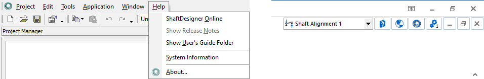
2.3. Help Toolbar
Most of the Help menu functions are moved to the upper right corner of the window and permanently available for the user. The user’s guide is updated according to the interface changes and new features.
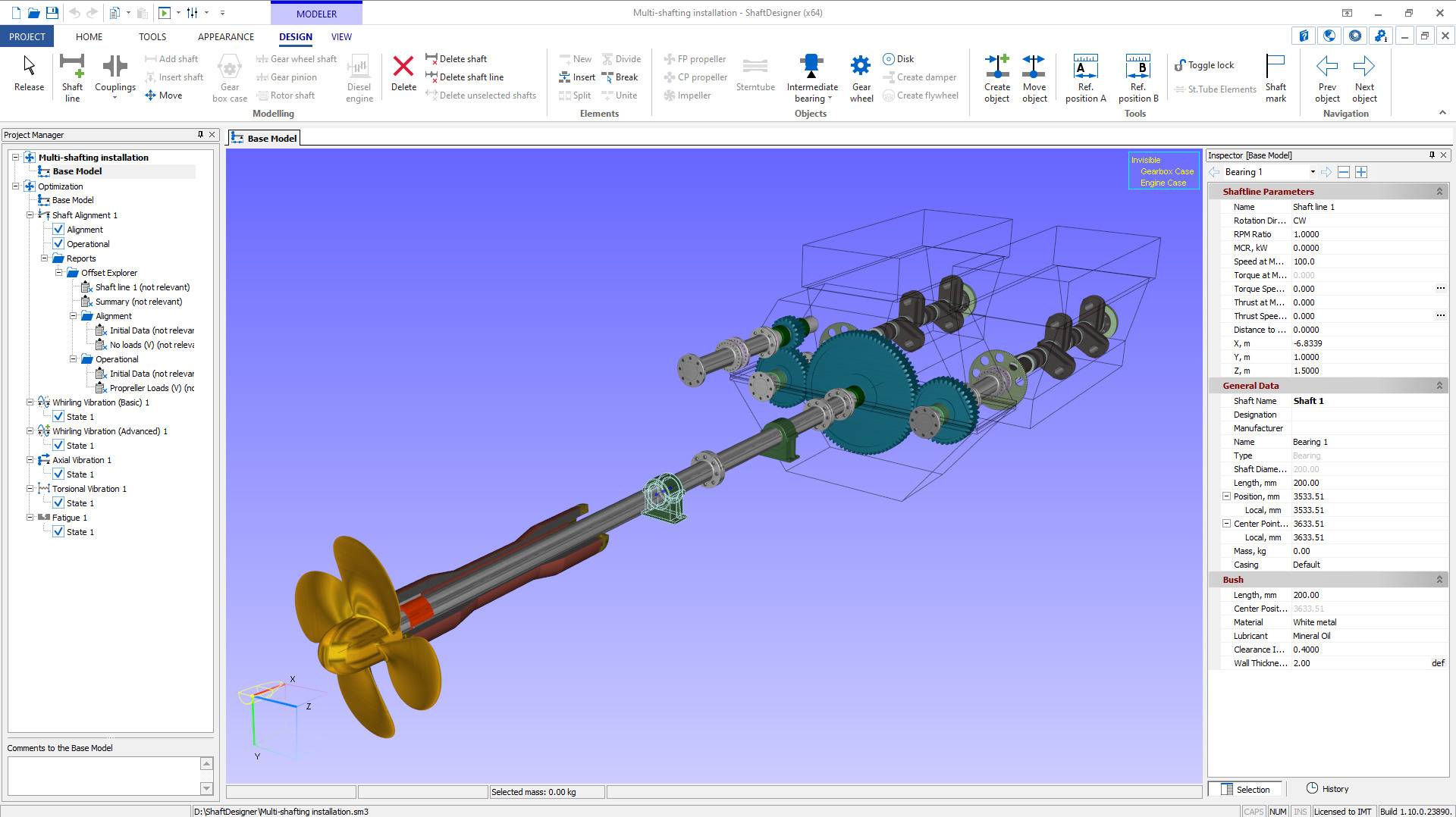
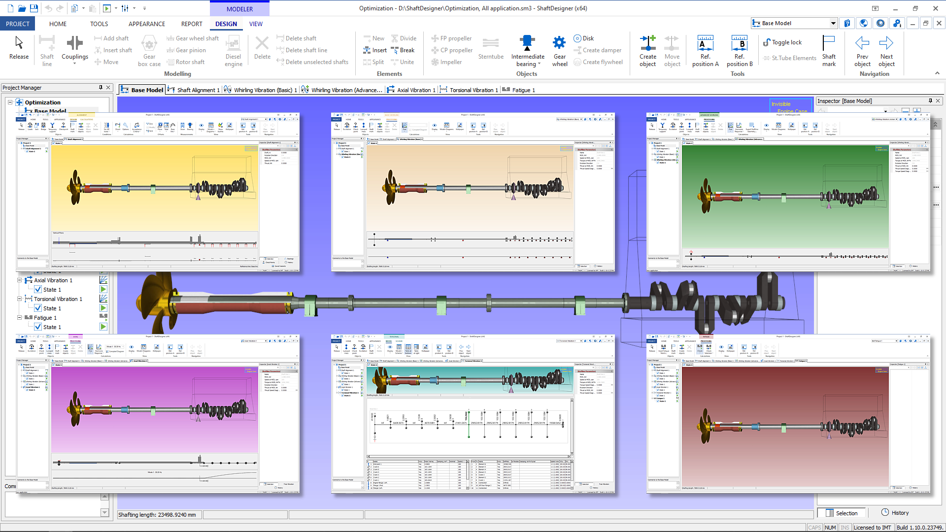
2.4. The Main Window
Almost all toolbars and menus were replaced with a modern ribbons tab in the upper part of the window. The ribbon contains several tabs designed to provide different features. Buttons are automatically collapsed depending on the window size.
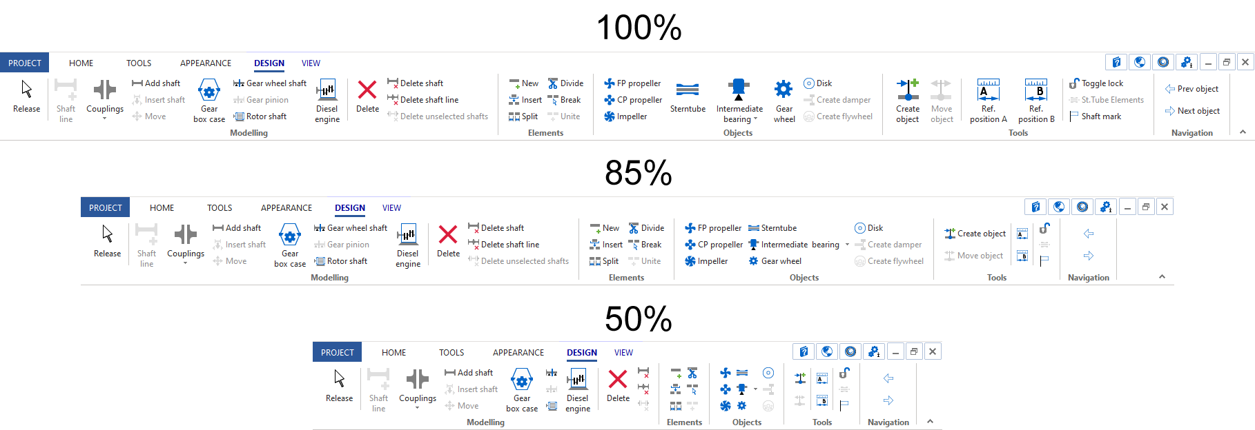
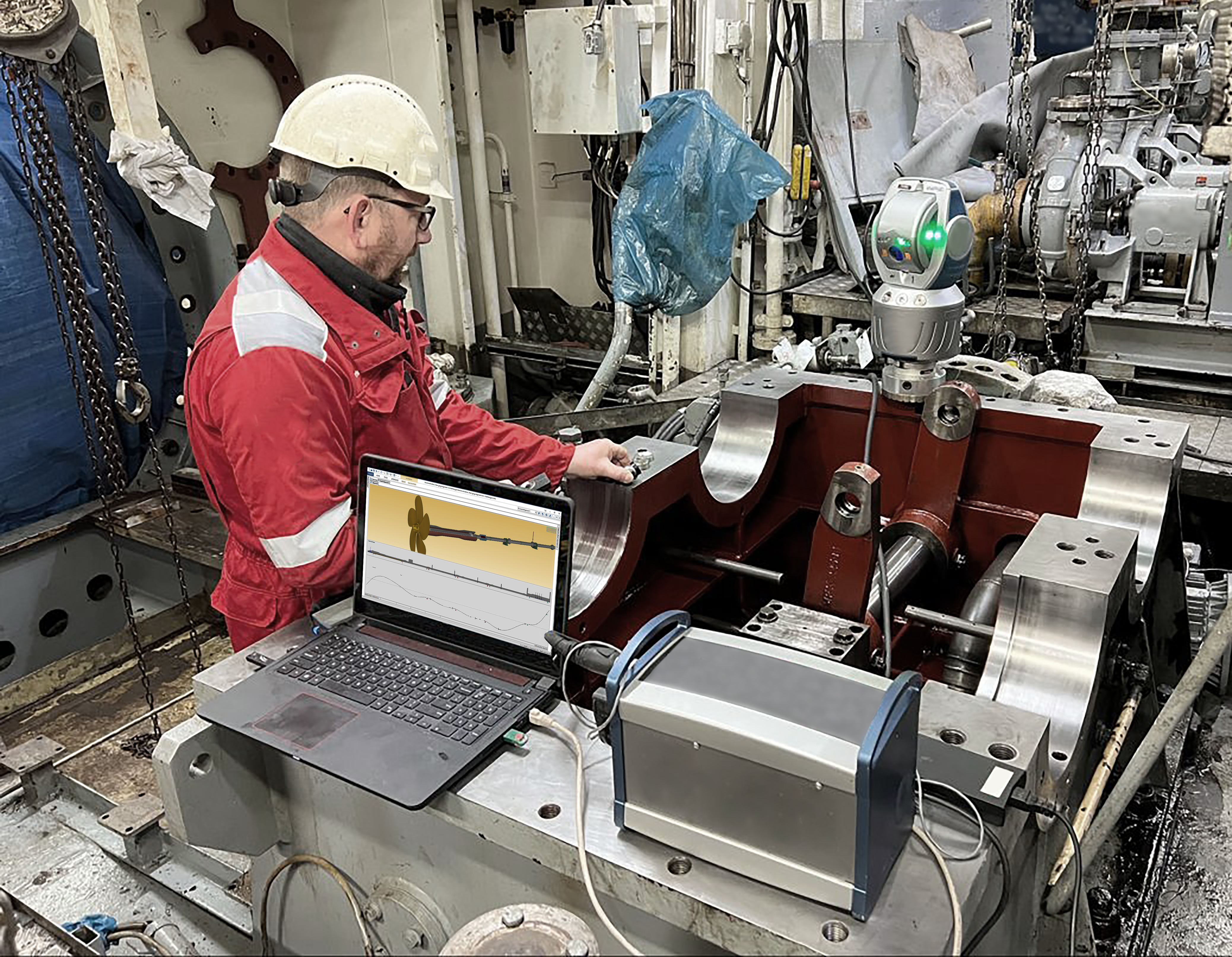
These ribbons can be hidden, as well as the Project Manager and Object Inspector. It makes ShaftDesigner convenient to use on portable laptops with small screens. For instance, it is very helpful onboard in the Engine Room. Also, we optimized the workflow for the multiscreen systems.
2.5. Common Ribbon Tabs
The Home, Tools and Appearance tabs contain the general software functions that are not application-specific.
The Home tab contains the basic functions and allows creating calculation applications:

The Tools tab is responsible for the repository, project data, material and media library, new project settings, units, and other options of the software.

The Appearance tab allows the user to manage the desktop and arrange the windows.

2.6. Modeler Tabs
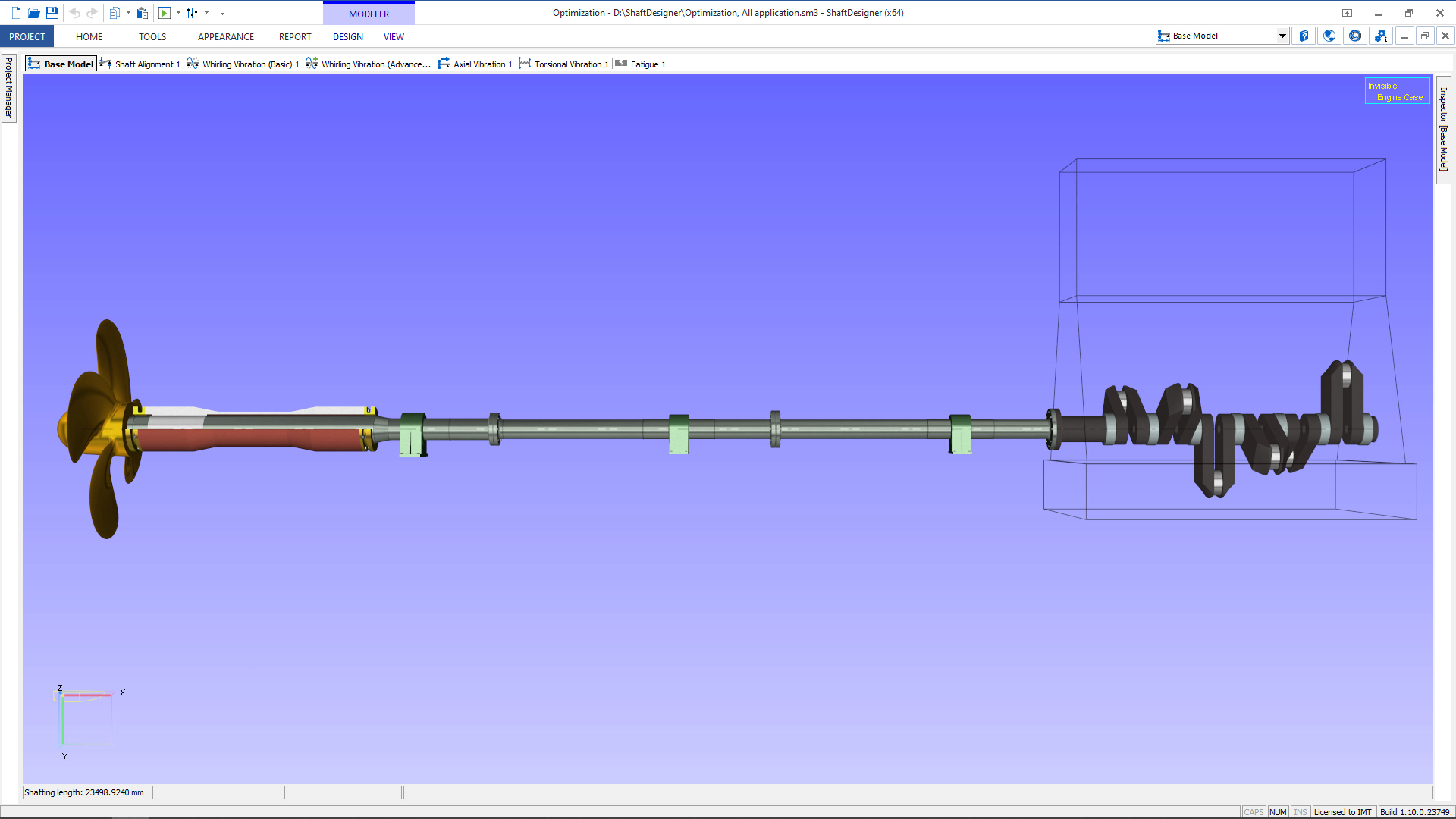
The Modeler and application windows introduce their own tools. The Modeler’s Design tab provides all tools for creating and editing the Base model.

The View tab allows adjusting displayed objects, controlling the view, and changing appearance settings.

2.7. Applications’ Tabs
Each module is marked by its own context color to improve the feeling of the software. The active application can be switched in the drop-down list in the upper right corner, in the Project Manager or in the window tabs. Every user can find the best way to switch between the applications.
2.7.1. Alignment Application
The Shaft Alignment application operates with 2 own tabs: Design and Calculations. The Design tab allows adding specific objects, setting up propeller hydrodynamic loads, calculation options, acceptance criteria, bearings’ offsets, measurements and adjusting view settings.

The Calculations tab contains all functions related to the Shaft Alignment. This allows the user to find, set up and run the specific task easily. However, all the calculations are also accessible from the Design tab by the special drop-down menu.

2.7.2. Whirling, Axial Vibration and Fatigue Applications
The Whirling Basic and Advanced, Axial vibration and Fatigue applications operate with the single Processing tab. It provides buttons to create the additional objects, tune and run the calculation, change the view.


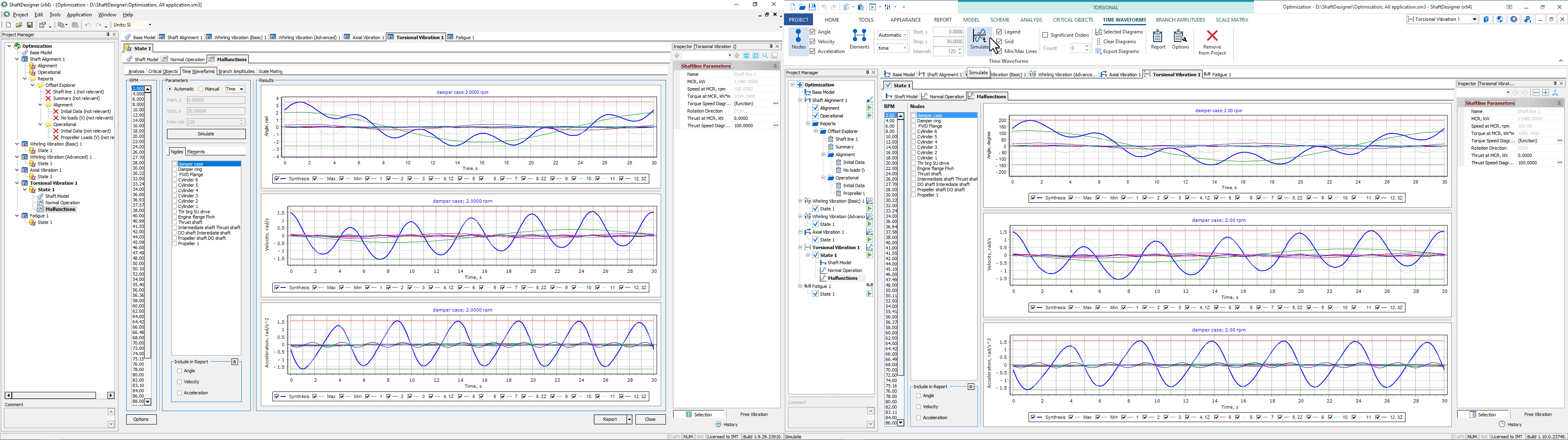
2.7.3. Torsional Vibration Application
The Torsional vibration application uses the Model and Scheme tabs. The first one is intended for shafting model operations.

The second one is designed for creating and editing the Mass-Elastic system, scheme branches, the Power Table and changing the view. The Scheme tab also contains the buttons to run the Torsional Vibration Analysis.

2.7.4. Vibration Calculation Results Tabs
After the vibration analysis calculation was carried out, the various results are shown as a special Browser which has its tabs. In contrast to the previous version, all parameters, view and reporting functionality is moved to these tabs to simplify the reports’ generation. This approach gives an additional screen space for the plots and diagrams.
Now let’s review the most important new features of ShaftDesigner.
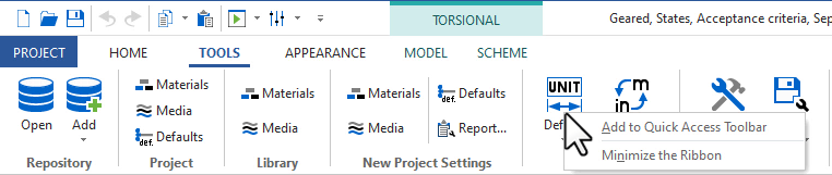
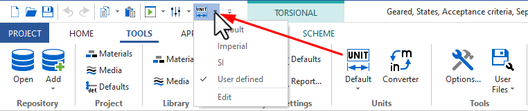
3.1. Quick Access Toolbar
It is possible now to add the most frequently used commands to the Quick access toolbar to activate them at any time.
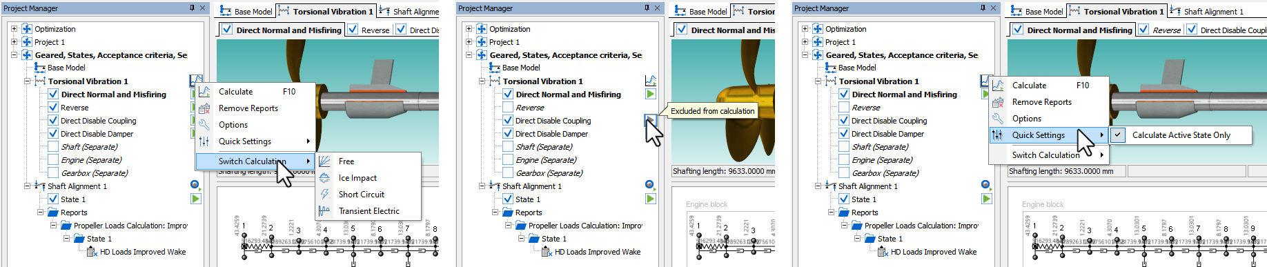
3.2. Project Manager Tools
The Project Manager got the new feature, making it a powerful and rapid control center. Now, the operating state can be easily disabled or excluded from the specific calculation. There is also an option to run the computation for the active state only. It is available from the calculation menu or quick access toolbar. You don’t have to open the Calculation Options window to manage operating states to run.
Also, you can run the computation, open the options window or switch between the calculation types just in a couple of mouse clicks without seeking the appropriate buttons in the User’s Interface.
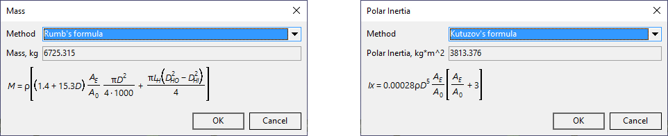
3.3. Propeller Mass, Inertia and Buoyancy Approximate Methods
The default propeller mass and inertia calculation were updated and extended. Now each parameter has several approximate methods with a clear formula. It allows estimating the absent initial data in a more reasonable way. Mass properties are automatically recalculated with the changed propeller parameters if the approximate formula is chosen.
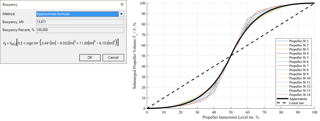
Also, the propeller buoyancy can be determined by a new approximate formula for a partially submerged propeller, depending on propeller immersion level. It was created by our research and development department based on a statistical approach, see our article for more information.
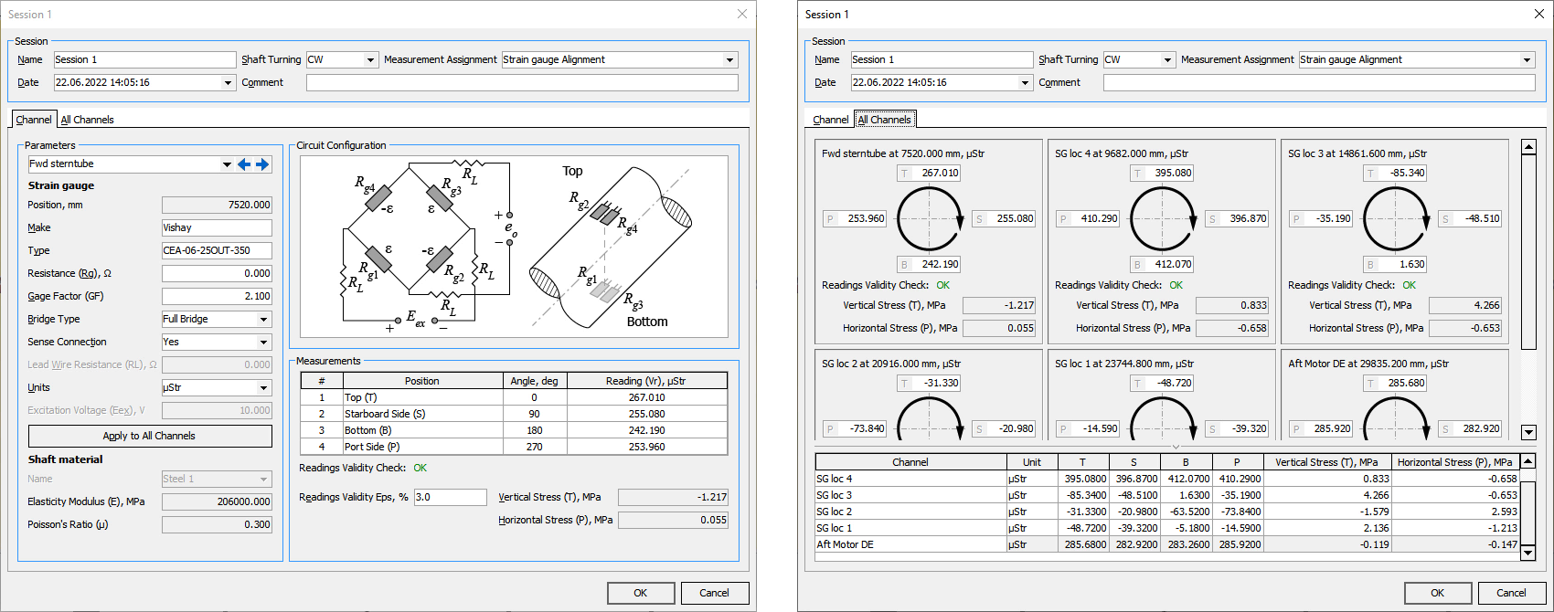
3.4. Strain Gauge Measurements
We introduce the absolutely new tool for strain gauge measurements processing. The practical engineering work is the base for this new tool. All measurements can be stored directly in the project.
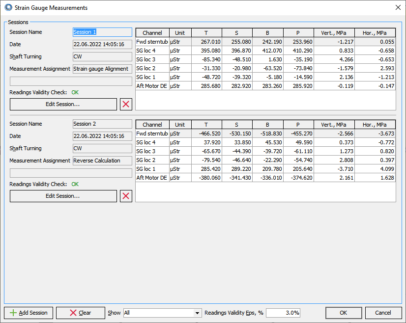
Moreover, measured strains or millivolts can be converted to stresses automatically, taking into account the bridge’s configuration. We eliminated any kind of hand calculations to prevent errors. Calculated stresses can be used in reverse calculation and strain gauge alignment. However, it is still possible to enter stress manually.
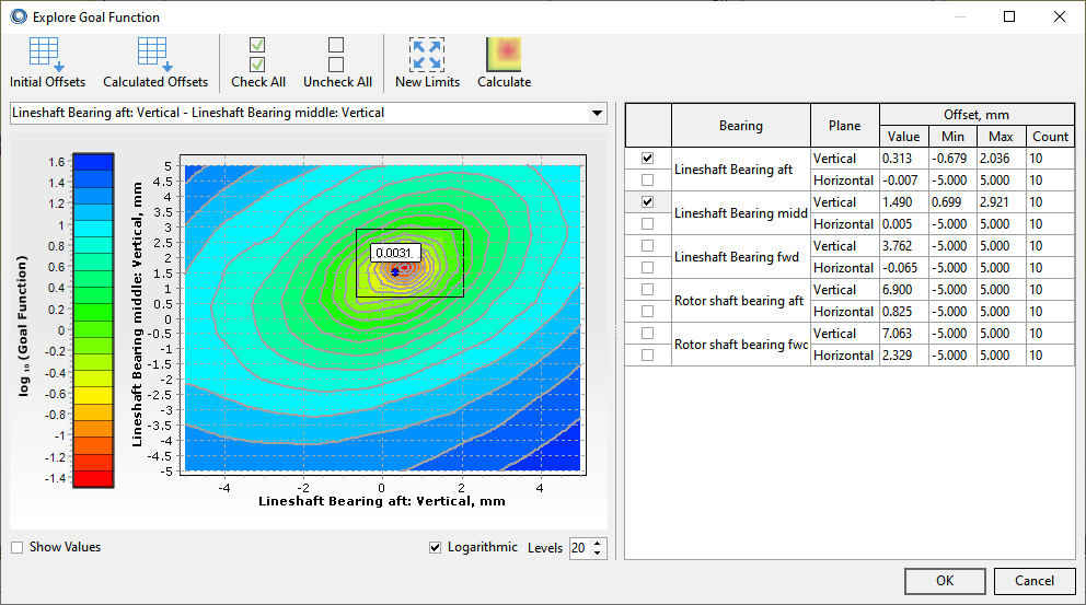
3.5. Reverse Calculations
The reverse calculation is significantly improved. In addition to the updated window with more convenient and structured buttons, the calculation algorithm became more efficient in searching for actual bearings’ offsets based on the different kinds of measurements.
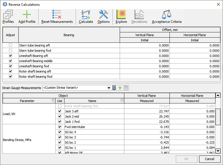
Also, a new explore goal tool allows researching or adjusting the solution manually in case of advanced projects.
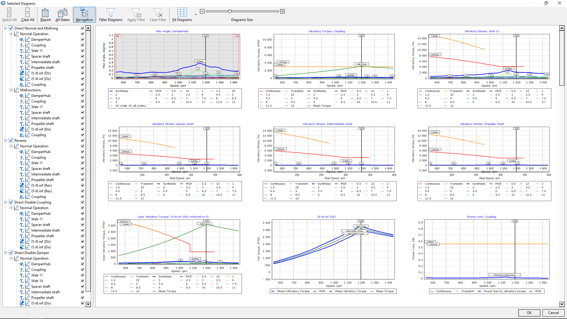
3.6. Selected Diagrams
The analysis of the forced vibration results now is more convenient with a new selected diagrams window. It shows preview of all diagrams that will be included in the report, allows comparing diagrams for different elements or nodes, parameters and calculation states. The report can be generated directly from the window.
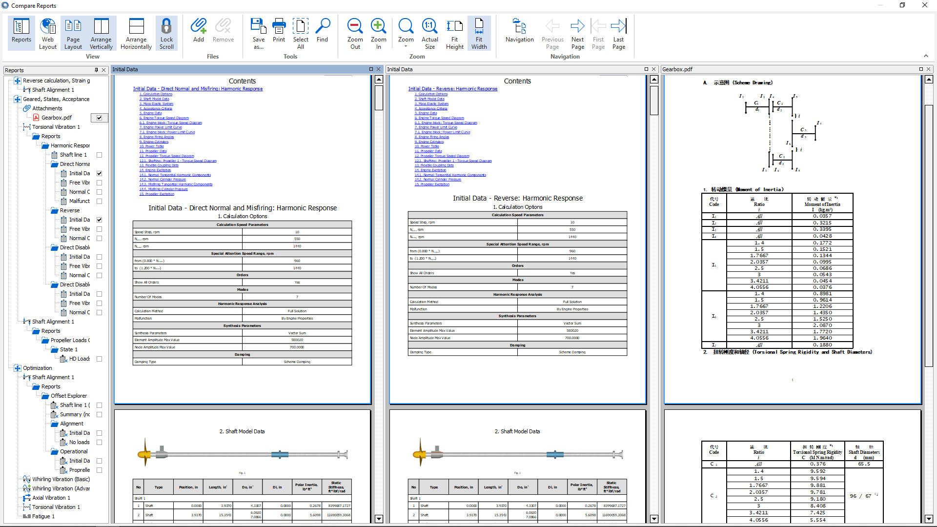
3.7. Compare reports
The next great new tool is the reports’ comparison. It is easy to open several reports in a single window, scroll them synchronously (if necessary) and compare in a convenient way. This tool also supports PDF files attached to the project and even external PDF files. This tool is brilliant if you need to check the reports made from the different states, projects or even 3rd party documents.
There is a summary of main changes in the new version:
- Enhanced ribbon user’s interface
- Program options window redesign
- Project manager calculation control
- Approximate propeller methods
- Strain gauge measurement tool
- Reverse calculation improvements
- Selected diagrams window
- Compare reports tool
At last, there are some important final notes. The main features of the ShaftDesigner software is the same as you got used to. The projects created in the previous version are fully compatible with ShaftDesigner 1.10. The new update is now available for all subscribed customers with active service contract, the new customers and the users with temporary license. Also, you can try the new version in a free trial full-functional version from our website www.shaftdesigner.software. We encourage you to try the new updated ShaftDesigner software now and contact us if you have any questions or suggestions.