RAPID METHOD FOR ACCURATE DETERMINING PROPELLER VOLUMETRIC AND INERTIA PROPERTIES
Ursolov Oleksandr Ihorovich, Ph.D., Filin Dmytro Sergeevich, M.Sc.
Abstract. The calculation tool for rapid and accurate determining the propeller mass, centroid coordinates, and inertia moments was developed. The approximate formulas for the propeller’s diametrical inertia moment and partially submerged volume have been proposed. The results are dedicated to increase accuracy of the initial data for shaft alignment and vibration calculations.
Keywords: propeller, mass characteristics, software, shafting alignment and vibration.
Introduction.
One of the most important objects in the marine propulsion shafting alignment and vibrations calculations is a propeller. Its volumetric and inertia properties have a significant impact on the calculation results: bearing loads and misalignment, shaft stress, vibratory amplitudes etc.
The propeller is located on the cantilever end of the propeller shaft. Its location and great weight cause the significant shaft misalignment in the aft stern tube bearing. The longitudinal coordinate of the propeller’s gravity center can also influence the value of bearing misalignment. At the same time, the buoyancy force acting on the propeller tend to unload the aft stern tube bearing. During shaft alignment procedure, the propeller can be partially immersed due to lightweight ship loading condition. Also, propeller mass, polar and diametrical moment of inertial have significant impact on the axial, torsional and whirling vibrations of the marine propulsion shafting.
There are several ways to assess the propeller’s volumetric and inertia properties. The most accurate one is to calculate these characteristics in one of the CAD systems such as Rhinoceros, SolidWorks, AutoCAD etc. out of the exact 3D model. However, at the alignment and vibration calculation stage a propeller’s 3D model usually is not available for the engineer as well as whole information about its mass characteristic. Sometimes, the propeller drawing is available, but building a 3D model out of the drawing could require time that is comparable with the shaft alignment or vibration calculation itself. That is why engineers use approximate approaches to assess propeller characteristics:
- Mass is calculated by the approximate empirical formulas [1];
- Polar inertia moment is calculated by the approximate empirical formulas [2, 3];
- Diametrical inertia moment is assumed to be a half of polar inertia moment;
- Center of the propeller’s mass is supposed to be in the middle of the hub’s length;
- Immersed volume is to be calculated in the proportion to the immersion level.
The big advantage of the approximate formulas is the rapid result. However, these formulas do not take into account the exact geometry of the propeller. That is why approximate formulas could lead to significant errors of the propeller volumetric and inertia characteristics and as a result – to error in shaft alignment and vibration calculations.
The aim of the present research is to develop an engineering tool for rapid and accurate determining the propeller center of gravity, mass, polar and diametrical inertia moments, immersed volume based on the restricted amount of information about the propeller or the propeller drawing.
Methodology.
The program with the user interface (Fig. 1) has been developed for assessing volume, mass, centroid coordinates and inertia moments of the propeller as well as automatic building the propeller’s 3D model. General geometric propeller parameters and the detailed geometry are used as initial data:
- Propeller diameter D, m;
- Number of blades, Z;
- Rotation direction;
- Expanded blade area ratio AE/A0;
- Pitch of the blade, P, m;
- Rake angle;
- Fillet radius;
- Hub length Lh, m;
- Outer diameter Dh, m, in intermediate, aft and forward sections;
- Inner hub geometry (piece wise linear function of inner hub diameter, Di, m)
- Blade sections geometry for different relative radii:
- Blade section chord length;
- Pitch of the section;
- Maximum thickness;
- Maximum camber;
- Position of maximum camber;
- Skewness.
When blade sections geometry is not available, the Wageningen B-series propeller geometry can be generated for specified D, Z, AE/A0 and P [4, 5].
The propeller blade geometry is built by the traditional formulas used in the propeller design [5, 6]. The blade section is approximated by the analytical expression [7] in order to reduce the amount of the required initial data. The offset is added to the sections’ counters near the hub to develop fillet. The outer surface of the propeller hub is approximated by Akima approximation out of 3 sections’ diameters. The inner hub surface is build out of aft and forward inner diameters or table of diameters to match the propeller drawing.
The specialized data structure was developed and implemented to create and operate with 3D models, specifically marine propellers. This data structure consists of three general objects – nodes, faces and bodies that are in the relation with each other. A node contain coordinates in the virtual space, a face consists of several nodes (three or more), a body consists of faces. An algorithm of triangulation was implemented to provide simplification of complex faces topology. In addition, an algorithm of 3D model subdivision by arbitrary plane was implemented. This gives the possibility to get separate bodies of wet and dry parts of a partially submerged propeller (Fig. 2). The 3D model is visualized using OpenGL technology, the geometry also can be exported to the STL file, for example for using in CFD simulations. The developed algorithm for 3D modelling is general and in the future can be used to solve problems that is not related to the propeller geometry.
Fig. 1 – User’s interface
Fig. 2 – Partially submerged propeller (60%)
The general method for calculating geometric characteristics of 3D polygonal objects [8] has been implemented in order to assess geometric characteristics of the propeller’s 3D model. This method allows determining volume, centroid coordinates, inertia moments of an arbitrary close facet 3D geometrical object, for example a marine propeller.
Results.
In this research, geometrical characteristics of 14 different existing propellers (Fig. 3) were studied. Their main parameters and inertia characteristics are shown in the Table 1. The relative error of calculation using different approaches are shown in the Table 2. As can be seen, the developed method provides accurate enough results. Formulas for the propeller mass and polar inertia moment provided in [1] and [3] correspondingly also gives reasonable results.
The calculated values of polar Ix and diametrical Iy(Iz) inertia moments allow to develop an approximate relation between them for typical marine propellers: Iy = Iz ≈ 0.6 Ix. This approximate formula allows more accurate assessing the diametrical inertia moment using the approximate formulas for the polar inertia moment.
Fig. 3 – Propellers used in the research
Table 1 – Propellers’ parameters
| №
|
D
m |
Z
|
AE/A0
|
Lh
m |
Dh,
m |
ρ
kg/m3 |
M 1
kg |
Ix1
kg.m2 |
M 2
kg |
Ix2
kg.m2 |
Iy= Iy2
kg.m2 |
M 3
kg |
M 4
kg |
Ix5
kg.m2 |
Ix6
kg.m2 |
|
| 1 | 1.600 | 3 | 0.500 | 0.420 | 0.342 | 7850 | 410 | – | 404 | 40.1 | 24.2 | 381 | 379 | 41.9 | 39.5 | |
| 2 | 1.000 | 4 | 0.550 | 0.300 | 0.188 | 7600 | – | – | 96.2 | 3.25 | 2.15 | 90.0 | 93.3 | 4.00 | 4.07 | |
| 3 | 1.300 | 4 | 0.634 | 0.240 | 0.188 | 8300 | – | – | 157 | 14.3 | 7.58 | 216 | 182 | 14.9 | 19.5 | |
| 4 | 1.575 | 4 | 1.175 | 0.700 | 0.230 | 7600 | 625 | 89.54 | 588 | 65.3 | 49.2 | 352 | 578 | 38.8 | 99.2 | |
| 5 | 1.700 | 4 | 0.850 | 0.335 | 0.321 | 7600 | 612 | 96.77 | 432 | 68.3 | 38.3 | 442 | 517 | 56.8 | 96.9 | |
| 6 | 1.800 | 4 | 1.000 | 0.450 | 0.368 | 7600 | – | – | 689 | 113 | 67.8 | 525 | 771 | 75.6 | 158 | |
| 7 | 2.850 | 4 | 0.594 | 0.608 | 0.809 | 7600 | – | – | 2586 | 735 | 437 | 2083 | 2658 | 752 | 837 | |
| 8 | 5.600 | 4 | 0.700 | 1.350 | 1.120 | 7600 | – | – | 18696 | 24495 | 14147 | 15805 | 17726 | 22029 | 29747 | |
| 9 | 1.350 | 5 | 1.100 | 0.300 | 0.213 | 7600 | 346 | 32.629 | 311 | 30.4 | 17.1 | 221 | 311 | 17.9 | 42.2 | |
| 10 | 1.800 | 5 | 0.550 | 0.430 | 0.315 | 7600 | 573 | 89.45 | 474 | 69.1 | 40.1 | 525 | 452 | 75.6 | 76.9 | |
| 11 | 1.980 | 5 | 0.550 | 0.480 | 0.414 | 7900 | 1021 | 180.49 | 889 | 153 | 89.4 | 726 | 727 | 122 | 129 | |
| 12 | 7.900 | 5 | 0.800 | 1.612 | 1.422 | 7600 | – | – | 43984 | 134218 | 73891 | 44374 | 46245 | 123082 | 195077 | |
| 13 | 8.250 | 5 | 0.795 | 1.650 | 1.456 | 7600 | 62950 | 219025 | 56323 | 178785 | 97669 | 50536 | 54041 | 152873 | 240462 | |
| 14 | 10.200 | 6 | 0.870 | 2.250 | 1.934 | 7600 | 123410 | 641735 | 112787 | 560362 | 308420 | 95509 | 113696 | 441632 | 775227 | |
| 1 The data from the propeller’s drawings | ||||||||||||||||
| 2 The calculated values by the proposed method | ||||||||||||||||
| 3 M = 90D3ρ/7600 | ||||||||||||||||
| 4 M = ρ {(0.025 (1.4 + 15.3 D) AE/A0 π D2 + 0.6 Lh (Dh2 – Di2)}, [1] | ||||||||||||||||
| 5 Ix = 4 D5, [2] | ||||||||||||||||
| 6 Ix = 0.0002744 AE/A0 (AE/A0 + 3) ρ D5, [3] | ||||||||||||||||
Table 2 – Propellers’ mass and polar inertia moments calculation error
| № | M 2/M 1, % | M 3/M 1, % | M 4/M 1, % | Ix2/ Ix1, % | Ix5/ Ix1, % | Ix6/ Ix1, % |
| 1 | -1.6 | -7.1 | -7.5 | – | – | – |
| 4 | -6.0 | -43.7 | -7.6 | -27.1 | -56.7 | 10.7 |
| 5 | -29.5 | -27.8 | -15.6 | -29.5 | -41.3 | 0.1 |
| 9 | -10.1 | -35.9 | -10.0 | -6.8 | -45.0 | 29.3 |
| 10 | -17.3 | -8.5 | -21.1 | -22.8 | -15.5 | -14.0 |
| 11 | -13.0 | -28.9 | -28.8 | -15.1 | -32.6 | -28.6 |
| 13 | -10.5 | -19.7 | -14.2 | -18.4 | -30.2 | 9.8 |
| 14 | -8.6 | -22.6 | -7.9 | -12.7 | -31.2 | 20.8 |
Fig. 4 – Submerged volume vs. rotational angle (Propeller № 2)
The static buoyancy of the partially immersed propeller depending on the propeller phase angle and immersion level was studied. Buoyancy force is proportional to the submerged volume, water density (ρw = const.) and acceleration of gravity (g = 9.81 = const.). It is enough to research the submerged volume of the propeller because only this value varies with the propeller rotation and changing its submergence. The dependence of the submerged volume on the immersion and rotation angle for the 4-blades propeller model № 2 is shown on the Fig. 4. As can be seen, the relative submerged propeller volume and correspondingly buoyancy force vary with the propeller rotation. This variation is more significant for the immersions 20-45% and 55-80% (Fig. 2). It is important that during shaft alignment procedure, the level of propeller immersion 60-80% frequently takes place, especially for large cargo ships. It shows the significance of the developed tool spreading light on this uncertainty during shaft alignment calculation.
The Fig. 5 shows the dependence of submerged volume on the immersion level for all studied propeller models, the values are been phase angle-averaged. It can be clearly seen that for all propellers the dependence is non-linear. Moreover, at the immersions approximately 40 and 60%, where the hub comes in and out of the water, the curves have knuckle points. The values correspond to the linear low only at the immersion 0, 50 and 100 %. The error of the linear assumption could reach 27% of the full submergence buoyancy. In order to reduce this error, the approximate polynomial formula was developed using the least square method:
\({\small {V_s}=V\left[0.5+\rm{sign}(Im-50) \left(3.441\overline{Im}-9.302 \overline{Im}^2+11.890\overline{Im}^3+6.103\overline{Im}^4\right)\right], }\)where V – total volume of the propeller, m3; \({\small \overline{Im}=|(Im-50)/100|}\) ; Im – level of the propeller immersion, %. The proposed formula reduces the possible error to 9%.
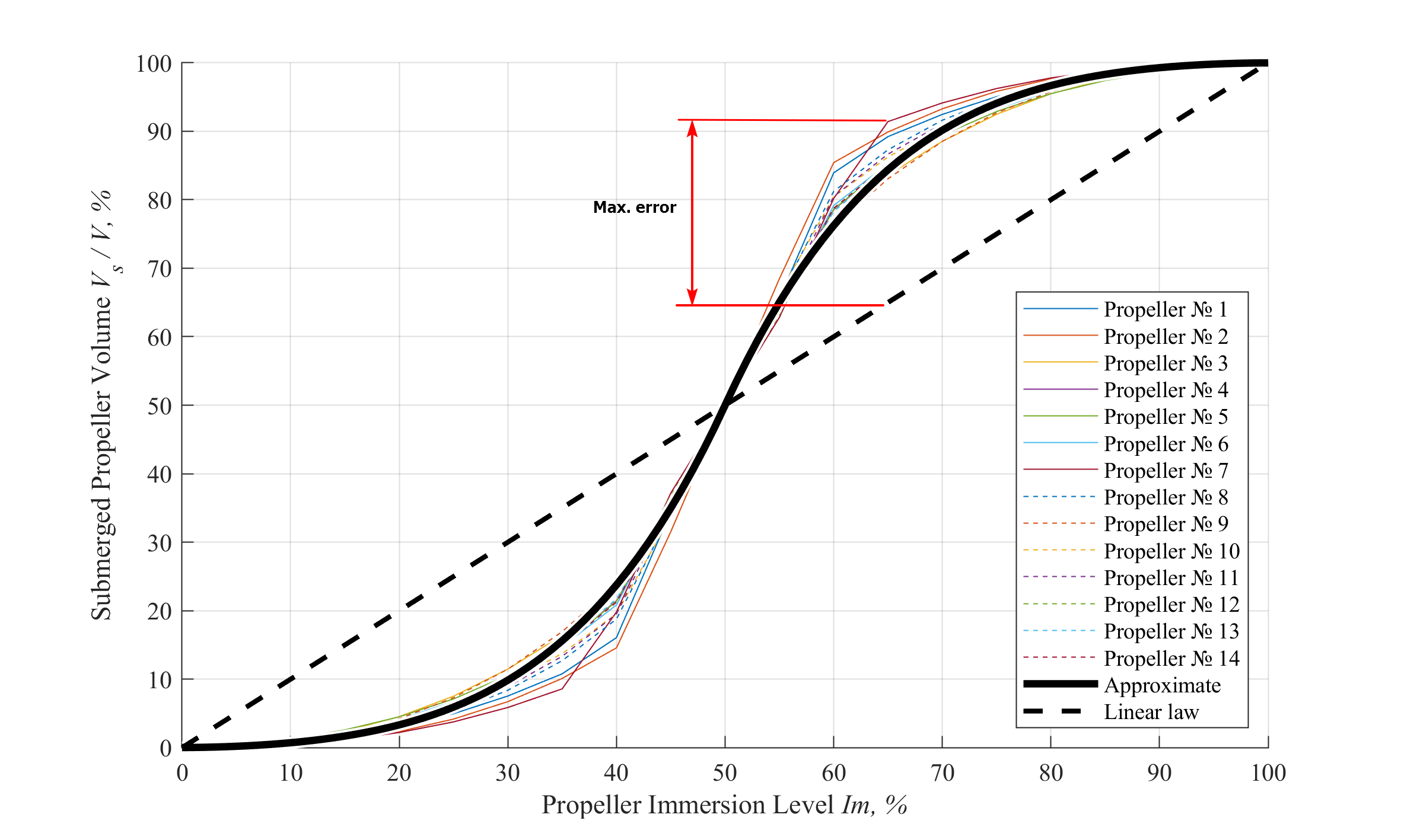
Fig. 5 – Submerged volume vs. immersion level
Conclusions.
The specialized automatic engineering tool for rapid and accurate propeller volumetric and inertia properties calculation has been developed. This tool allows determining the propeller’s mass, gravity centroid coordinates, polar and diametric inertia moments, submerged volume out of main propeller geometrical characteristics and, if available, blade sections’ geometry. This tool does not have restrictions that are typical for the approximate regression formulas, so can be used for unusual modern propeller designs.
The calculations for different propellers show good agreement with the mass and inertia moments mentioned on the drawings. The better accuracy of shaft alignment and vibration calculations can be provided using the developed program. Also, the recommendations for diametrical inertia moment and partially submerged propeller volume approximate estimation have been provided.
Both developed general method and proposed approximate formulas are to be integrated in the ShaftDesigner software [9] for marine propulsion shafting alignment and vibration calculations.
REFERENCES
[1] Ряйсянен, А. Г. (2010). Расчет движительного комплекса винтового судна. Хабаровск: ТОГУ. [2] Murawski, L. (2003). Static and dynamic analyses of marine propulsion systems. Warszawa: Oficyna Wydawnicza Politechniki Warszawskiej. [3] Ефремов, Л. В. (2007). Теория и практика исследований крутильных колебаний силовых установок с применением компьютерных технологий. Санкт-Петербург: Наука. [4] Oosterveld, M.W.C., Oossanen, P. van (1975). Further computer-analyzed data of the Wageningen B-screw series. International shipbuilding progress, vol. 20, No. 251, 3-14. [5] Carlton, J. S. (2019). Marine Propellers and Propulsion. Oxford: Elsevier. [6] Слижевский, Н. Б., Король, Ю. М., Соколик, М. Г., Тимошенко, В. Ф. (2004). Расчет ходкости надводных водоизмещающих судов. Николаев: НУК. [7] Ziemkiewicz D. (2016). Simple analytic equation for airfoil shape description. ArXiv: Fluid Dynamics. [8] Батрак, Ю. А., Чорний, Є. М. (2012) Обчислення геометричних характеристик полігональних й поліедральних клітинних комплексів. Вісник НУК, №4, 75-85. [9] ShaftDesigner –– The Shaft Calculation Software by IMT. (2021). Retrieved from https://shaftdesigner.software/