REVERSE ANALYSIS OF THE SINGLE STERN TUBE BEARING PROPULSION SHAFTING ALIGNMENT
Dr. Yuriy Batrak, Roman Batrak Intellectual Maritime Technologies August 2023
The ship repair industry demands reliable and easy procedures to verify shaft alignment of the ship propulsion shafting. These days this problem frequently arises due to the replacement of the propellers, the stern tube bearings lubricants, power reduction, etc. In such circumstances, it is impossible to perform the entire set of measurements as in the case of a newly built ship; engineers should rely on the reverse shaft alignment analysis results. There are three main techniques: the jack-up test, laser technology for the shafting deflection measurement, and strain gauges technology. The last one is preferable from any point of view, however, most of the shipyards are not ready yet to apply it. The laser technology is rather bulky and requires expensive hardware, so the old proven jack-up test procedure is still in use. However, in the case of shafting with a single stern tube bearing, the jack-up test results could be analyzed wrong, which is discussed below.
Let’s consider two recent cases Case-I and Case-II of the ships equipped with a single stern tube bearing having a propulsion shafting directly coupled to the diesel engine, Fig. 1.
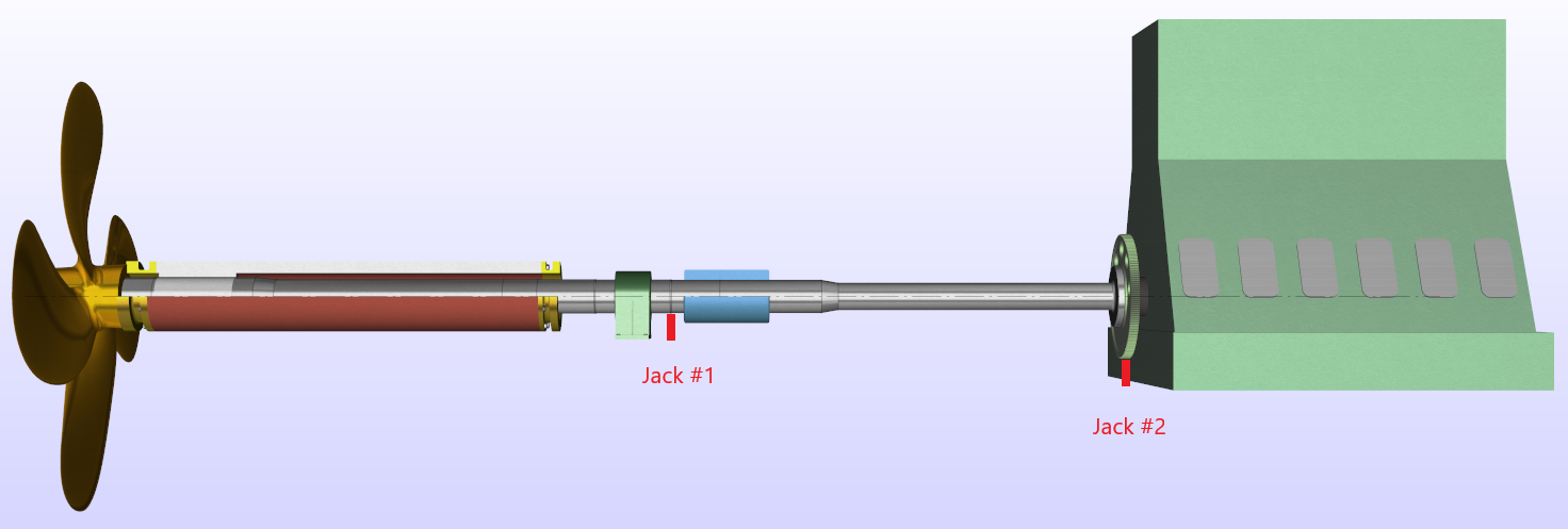
Fig. 1 Propulsion shafting
There are two hydraulic jacks installed for each case: the first one is located near the intermediate bearing, and the second is beneath the flywheel aiming to determine a load on the MB1 engine bearing. The engine’s aftmost crank was positioned in both cases in the Top Dead Center (TDC) for the first test and in the Bottom Dead Center (BDC) for the second test. All measurements were done for the ships’ afloat condition.
Case-I
Measurement results
The jack-up test results have a noticeable hysteresis, Fig. 2, Fig. 3. This is alarming and signals the presence of significant friction in the system during testing.
The second thing that attracts attention is the different results for the intermediate bearing in the BDC and TDC positions of the aftmost crank. Most probably, the reason is the different crankshaft stiffness in these extreme positions of the aftmost crank. Unfortunately, Class rules do not give any recommendation on how to proceed with this in such a situation. It should be noticed, that the crankshaft equivalent beam’s stiffness provided by the manufacturer does not depend on the aftmost crank position. It is possible that the equivalent beam corresponds to a specific position of the aftmost crank or is a result of averaging the crankshaft stiffness. Therefore, the current case showed a significant difference in the measurement’s results in two aftmost crank positions, that’s why reverse analysis must be performed separately for both of them.
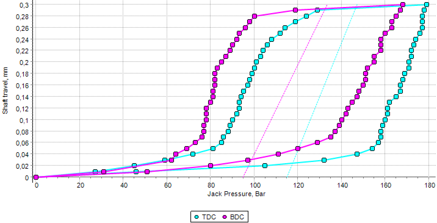
Fig. 2 Jack-up test diagrams for the intermediate bearing in the Case-I
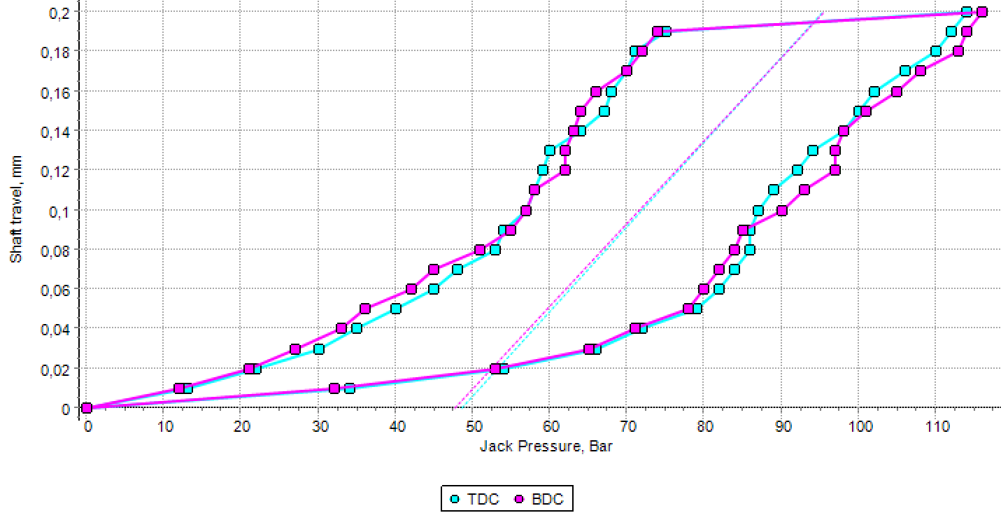
Fig. 3 Jack-up test diagrams attributed to the MB1 in the Case-I
Analysis
The ShaftDesigner software and its Jack-Up Test Simulation (JUTS) feature were used to analyze the jack-up test results. The shafting model was developed and the shaft alignment design was performed to determine the theoretical optimal initial offsets before the JUTS analysis. The results of JUTS using calculated optimal offsets are shown in Fig. 4 and Fig. 5. As can be seen, the theoretical lines (shown in red) do not fit the measured diagrams.
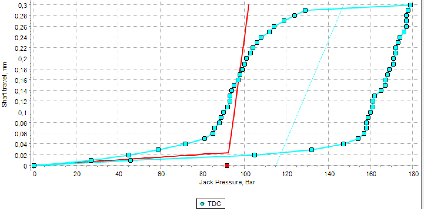
Fig. 4 JUTS result for the intermediate bearing in the Case-1
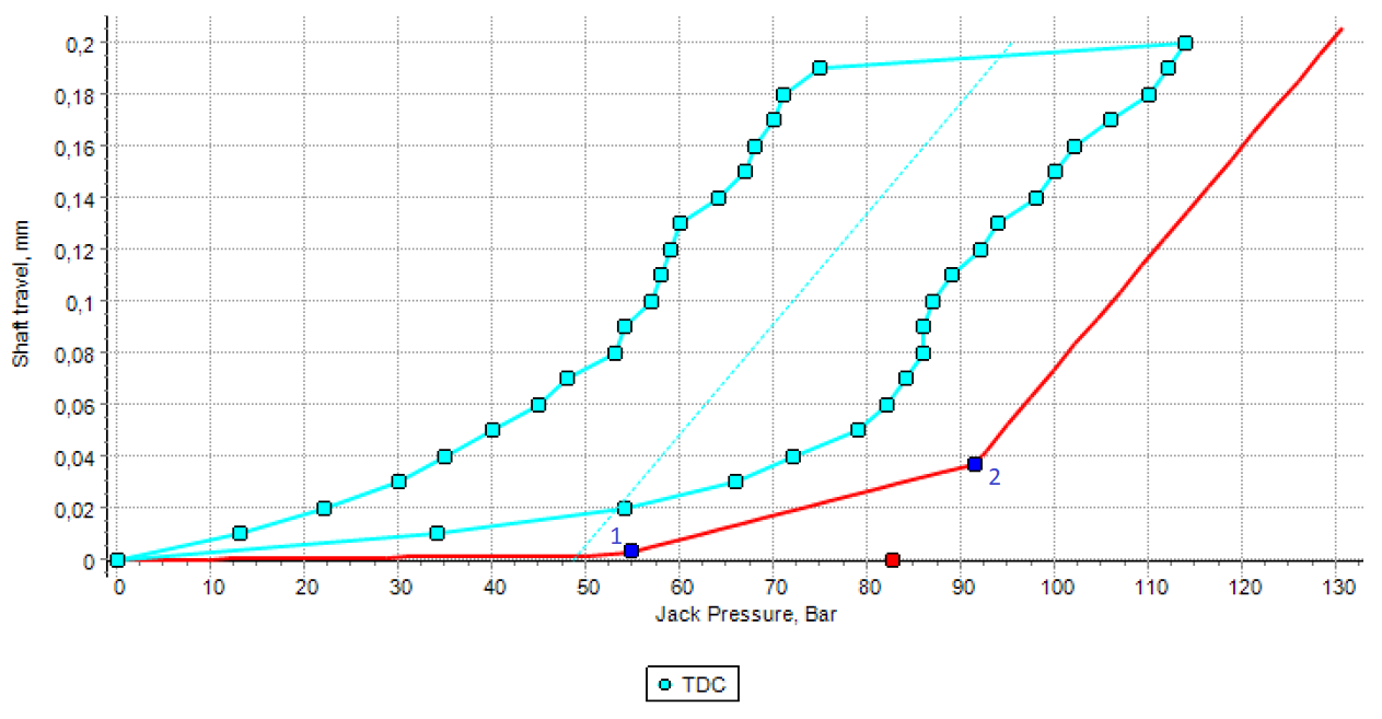
Fig. 5 JUTS result attributed to the MB1 engine bearing in the Case-1
JUTS analysis for the TDC position has shown the following:
- The calculated values of jack loads do not correspond resulting from the measurements. It means that actual bearing offsets do not correspond to theoretical optimal values.
- The intermediate bearing’s mean line slope on the jack-up test diagram is less than the slope of the theoretical line’s correspondent segment, i.e. the actual shafting stiffness during the jack-up testing is greater than the theoretically considered.
- The mean line slope on the jack-up test diagram attributed to the MB1 engine bearing is equal to the theoretical one.
- From pp. 2 and 3 above, it follows that something in the vicinity of the intermediate bearing stiffens the shafting.
As is known, the jack load is determined by the mean line started from the breakpoint where the shaft lost contact with the lower shell of the tested bearing. Such breakpoint for the MB1 on the theoretical line must be breakpoint 1 (see Fig. 5) but the theoretical line section is parallel to the mean line starting from breakpoint 2 at which the MB2 loses contact with the lower shell. So, the jack-up test diagram is valid for MB2 but not for MB1 as has been assumed.
As shown in Fig. 5, the jack-up test results attributed to the MB1 could push the shipyard engineer to make a wrong decision if operate the visual analysis only and does not use the JUTS procedure.
Indeed, there was no reason to doubt the theoretical graph’s calculation results for the intermediate bearing because the calculation scheme of the shafting is simple, so something else should be the reason. Taking into account significant hysteresis, we suspected the contact between the shaft and the sealing took place during the measurements.
After the elastic support was introduced at the sealing position, the slopes of the mean line and theoretical line became equal. The Reverse calculation procedure of the ShaftDesiger software was applied to determine the actual initial offsets of the shafting bearings and the engine crankshaft’s bearings.
Now, after the shafting model was updated, the JUTS’s results of both intermediate and MB2 engine bearings matched well, Fig. 6 and Fig. 7.
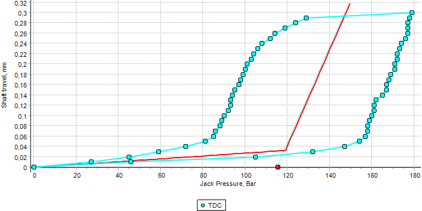
Fig. 6 JUTS result for the intermediate bearing in Case-1 after shafting model updating
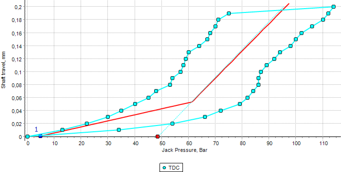
Fig. 8 JUTS result for the MB2 engine bearing in Case-I after the shafting model updating
It should be noted that the moment when the crankshaft loses contact with the lower shell of the MB1 engine bearing (brake point 1 in Fig. 8) happened at the very beginning of the measure at low jacking pressure. Therefore, it is not surprising that this fact is not visible on the measurement diagram. Subsequent direct shaft alignment calculation based on the real initial bearing’s offsets revealed that the load on this bearing is less than the allowable.
Case-II
Measurement results
The noticeable non-linearity of the Jack-up test for the intermediate bearing is noteworthy in Case II, Fig. 9.
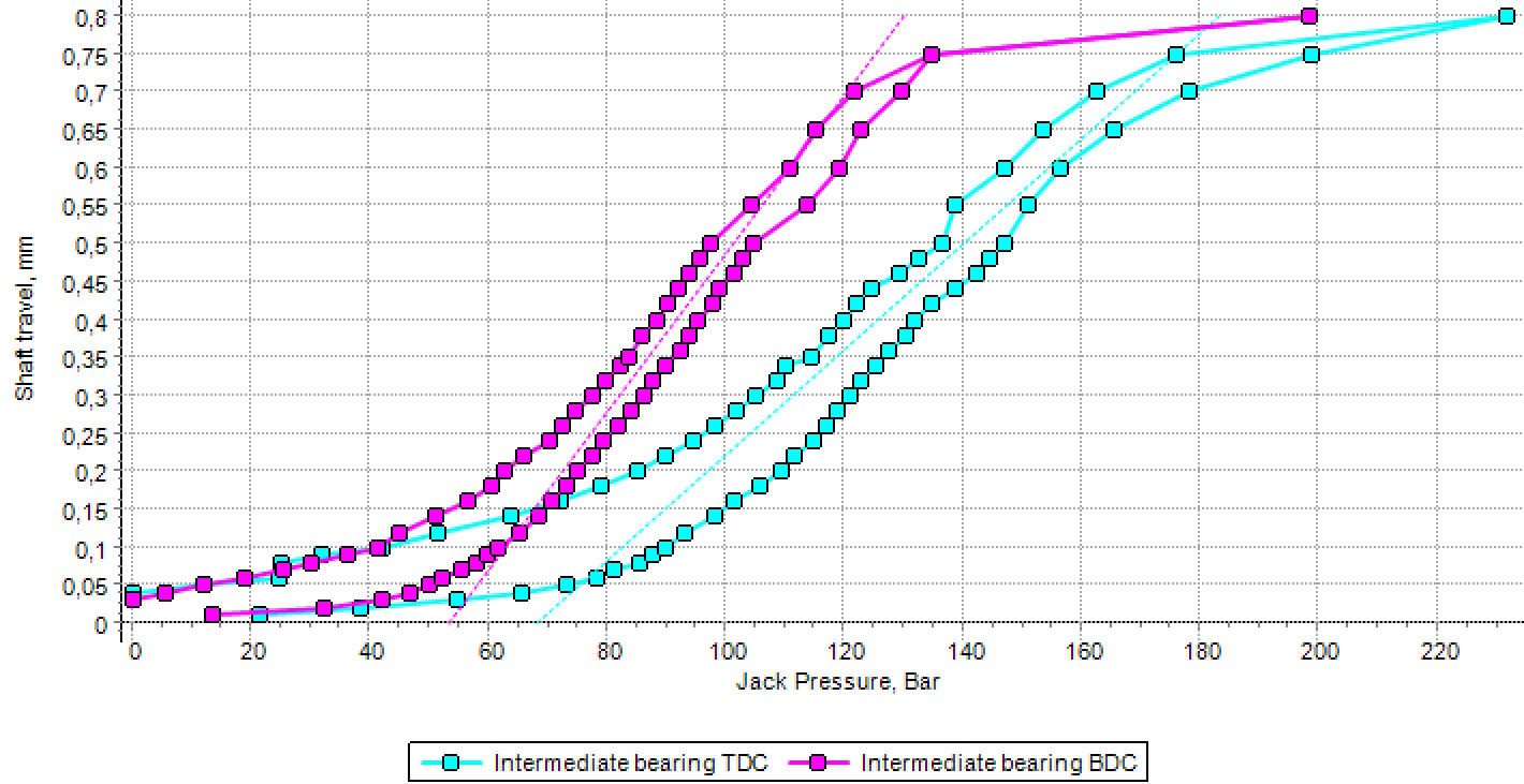
Fig. 9 Jack-up test diagrams for the intermediate bearing in the TDC and BDC position in the Case-II
The measurement results for MB1 engine bearing are practically the same in both TDC and BDC positions, Fig. 10.
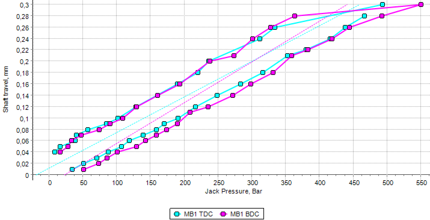
Fig. 10 Jack-up test diagrams for the MB1 in BDC and TDC position in the Case-II
Analysis
The aftmost crank intermediate bearing load in the TDC position is greater than in the BDC position. It should be noted that the same phenomenon was also observed in Case-I.
The jack-up test results do not depend on the position of the aftmost crank as in Case-I. The jack-up test diagram character shows that the MB1 bearing is unloaded.
The same analysis and model updating procedures were applied as in Case-I. After that the JUTS graph fits the measurement diagram well, Fig. 11.
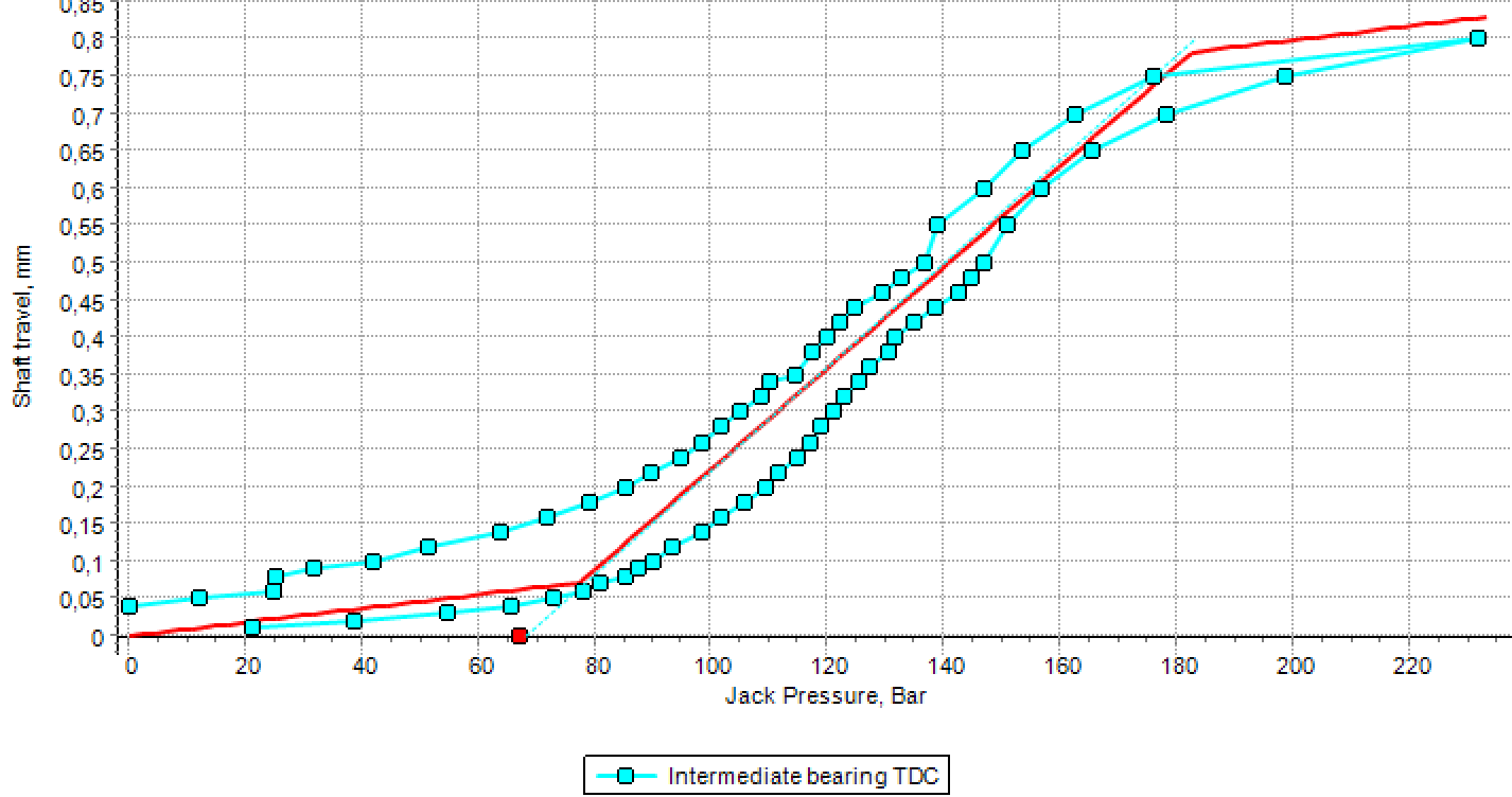
Fig. 11 JUTS result for the intermediate bearing in TDC position after shafting model updating
Lessons to be learned
- The theoretical graph of the jack-up test must be a part of the shaft alignment procedure documentation. The jack-up test measurement diagram’s visual analysis only with no theoretical calculation can lead to the wrong conclusions in some cases.
- During the jack-up test, special attention must be paid to the place of possible shaft contact with other disconnected shafting parts, any structures, or external equipment. It is required to eliminate unwanted contacts detected. A larger-than-usual hysteresis in the diagram may evidence the presence of such contacts.
- If necessary, the shaft contact with the sealing should be modeled as flexible support to improve the theoretical shafting model.
- According to the measurements the position of the aftmost crank (TDC or BDC) affects the intermediate bearing load. The TDC position gives a greater load. The reverse analysis should be performed for both positions.
- Position of the aftmost crank does not influence the engine’s main bearing load.
- The jack-up test simulation and shaft alignment reverse analysis features of software like ShaftDesigner allow reliable checking of the shaft alignment’s admissibility of the ship under repair based on the jack-up tests.