JAN 2016
ALIGNMENT
Machinery Sec 5
6.2 Stern tube bearings
6.2.1 Inside the stern tube the propeller shaft should normally be supported by two bearing points. In short stern tubes, the forward bearing may be dispensed with, in which case at least one free-standing journal bearing should be provided.
6.2.2 Where the propeller shaft inside the stern tube runs in oil-lubricated white metal bearings; or in synthetic rubber or reinforced resin or plastic materials approved for use in oil-lubricated stern tube bearings, the lengths of the after and forward bearings should be approximately 2 · da and 0.8 · da respectively.
The length of the after stern tube bearing may be reduced to 1.5 · da where the contact load, which is calculated from the static load and allowing for the weight of the propeller is less than 0.8 MPa in the case of shafts supported on white metal bearings and 0.6 MPa in the case of bearings made of synthetic materials.
6.2.2.1 Oil lubricated white metal bearings
The length of white-metal-lined, oil-lubricated propellerend bearings fitted with an approved oil-seal gland is to be not less than two times the required tail shaft diameter. The length of the bearing may be reduced, provided the nominal bearing pressure is not more than 0.80 N/mm2, as determined by static bearing reaction calculation taking into account shaft and propeller weight which is deemed to be exerted solely on the aft bearing, divided by the projected area of the bearing surface. The minimum length, however, is not to be less than 1.5 times the actual diameter
6.2.2.2 Oil lubricated synthetic material bearings
The length of synthetic rubber, reinforced resin or plastic oil-lubricated propeller end bearings fitted with an approved oil-seal gland is to be not less than two times the required tail shaft diameter. The length of bearing may be reduced, provided the nominal bearing pressure is not more than 0.60 N/mm2, as determined by static bearing reaction calculation taking into account shaft and propeller weight which is deemed to be exerted solely on the aft bearing, divided by the projected area of the bearing surface. The minimum length, however, is not to be less than 1.5 times the actual diameter. Where the material has demonstrated satisfactory testing and operating experience, consideration may be given to increased bearing pressure.
D
1. General
In addition to the design requirements addressed above, considerations are to be given to additional stresses in the shafting system given rise to by shaft alignment in relation to location and spacing of the shaft bearings, and by axial, lateral and torsional vibrations.
2. Fundamentals of Shaft Alignment
It has to be verified by alignment calculation that the requirements for shaft, -gearbox- and engine bearings are fulfilled in all relevant working conditions of the drive line. At this all essential static, dynamic and thermal effects have to be taken into account.
The calculation reports to be submitted shall include the complete scope of used input data and have to disclose the resulting shaft deflection, bending stress and bearing loads and must document the compliance of the specific maker requirements.
An instruction for the alignment procedure has to be issued describing the execution on board and listing the permissible gap and sag values for open flange connections or jack-up loads for measuring the bearing loads.
The final alignment on board has to be checked by suitable measurement methods in afloat condition in presence of the TL Surveyor.
In general, shaft alignment calculations, as well as a shaft alignment procedure, are to be submitted for reference. However, calculations for the following alignment-sensitive types of installations are to be submitted for review:
– Propulsion shafting of diameter greater than 300 mm.
– Propulsion shafting with reduction gears where the bull gear is driven by two or more ahead pinions.
– Propulsion shafting with power take-off or with booster power arrangements.
– Propulsion shafting for which the tail shaft bearings are to be slope-bored.
The alignment calculations are to include bearing reactions, shear forces and bending moments along the shafting, slope boring details (if applicable) and detailed description of alignment procedure.
The alignment calculations are to be performed for theoretically aligned cold and hot conditions of the shaft with specified alignment tolerances.
Calculations are to be performed for the maximum allowable alignment tolerances and are to show that:
– Bearing loads under all operating conditions are within the acceptable limits specified by the bearing manufacturer.
– Bearing reactions are always positive (i.e.,upporting the shaft).
– Shear forces and bending moments on the shaft are within acceptable limits in association with other stresses in the shaft.
– Forces and moments on propulsion equipment are within the limits specified by the machinery manufacturers. If he calculated relative misalignment slope between the shaft and the tail shaft bearing is greater than 0.3·10-3 [rad], then consideration is to be given to reducing the relative misalignment slope by means of slope-boring or bearing inclination.
TORSIONAL VIBRATION
Machinery Ch 4 Sec 6
A. General
1. Scope
This section applies to propulsion plants with the main propulsion engines having a power of not less than 75 kW when diesels are used and of not less than 100 kW when using turbo or electric drives, and to diesel generators as well as to internal combustion engines (ICE) driven auxiliary machineries having a primary engine power of not less than 100 kW.
Torsional vibration calculations is to be overcome both for the basic variant and for other variants and conditions possible in the operation of the installation as follows:
– Maximum power take-off and idling speed (with the propeller blades at zero position) for installations comprising controllable pitch propeller (CPP) or azimuth thrusters, – Individual and simultaneous operation of main engines with a common reduction gear,
– Reverse gear, – Connection of additional power consumers if their moments of inertia are commensurate with the inertia moments with of the working cylinder,
– Running with one cylinder misfiring, for installations containing flexible couplings and reduction gear, to be assumed not firing is the cylinder the disconnection of which accounts to the top degree for the increase of stresses and alternating torques,
– Damper jammed or removed where single main engine installations are concerned, – Any flexible coupling blocked due to breakage of its elastic components (where single main engine drive is concerned) vibration loads are the additional loads due to torsional vibrations. They result from the alternating torque which is superimposed on the mean torque.
3. Documents for approval
No calculations shall be submitted if it is proved that the installation is similar to that approved earlier or that its mass moments of inertia and its torsional stiffness between masses do not differ from the basic ones by ±10 and ±5% respectively. Calculations might be limited to determination of the natural frequencies if, at this stage of the calculation, it is established that the differences in the mass inertia moments and torsional stiffness between masses do not result in a change of the natural frequency of any one of the modes under consideration by more than 5%.
Design drawings, plans and particulars of rotating or harmonic moving system, partially or complete, are to be submitted to TL in triplicate for approval. The documents are required to contain the details of all the installation components:
– Particulars of engine, propeller, damper, flexible coupling, reduction gear, generator,etc.
– Layout of all installation operation conditions possible,
– Torsional vibration analysis for propulsion shafting systems for all modes of operation including the condition of one-cylinder misfiring,
– Natural frequency tables for all basic modes of vibration having a resonance up to 12th order inclusive within a range of between 0 and 120% of the rated revolution speed with relative amplitudes of masses and moments, and with scales of stresses (or torques) for all sections of the system, – Resonance amplitudes of the first mass of the system for each order of all vibration modes
– Resonance stresses (or torques) in all system components (such as shafts, reduction gear, couplings, generators, compression-key joints) for each order of all vibration modes, – Estimated temperature variation of the rubber components of flexible couplings as compared to relevant permissible values of the manufacturer for each order of all vibration modes, – The alternating torsional stress amplitude is understood as (max – min)/2 as it can be measured on the shaft in a relevant condition over a repetitive rotation, – Conclusions based on the results of calculation.
4. Symbols and Terms
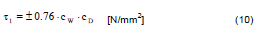
cD = Size (or scale) factor [-],
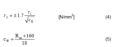
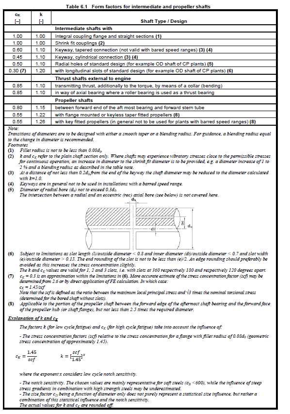
cK = Form factor for intermediate and propeller shafts depending on details of design and construction of the applied mechanical joints in the shaft line. The value for cK is given in Table 6.1 depending on the design [-],
cW = Material factor [-],
= (Rm + 160 ) / 18
d0 = Shaft diameter [mm],
D = Crankpin diameter [mm],
DG = Journal diameter [mm],
DBG = Diameter of bore in journal [mm],
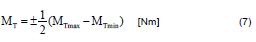
MT = Nominal alternating torque which is calculated by Formulae (7) [Nm],
MTmax = Maximum value of the torque [Nm],
MTmin = Minimum value of the torque [Nm],
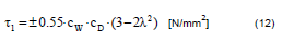
n = Speed under consideration. For tugs, trawlers and other ships which main engines run continuously under conditions of maximum torque at speeds below the rated speed throughout the speed range, n=no shall be adopted and Formulas (9) and (10) shall be used. For the main diesel generators of ships with electric propulsion plants, all the specified values of no shall, by turn, be adopted as n, and in each of the ranges 0.9<<1.05, Formulas (11) and (12) shall be used for partial loads [min-1],
no = Rated (nominal) speed [min-1],
Rm = Tensile strength of shaft material [N/mm2],
= 600 [N/mm2],for propeller shafts in general and for all other shafts (especially intermediate shafts) made of forged, low alloy carbon or carbon manganese steel,
= 800 [N/mm2],for all shafts except propeller shafts made of forged high alloy steels.
Formula (3) should be applied in conjunction with such steels and special design features only
WP = Polar moment of resistance related to crosssectional area of the section under consideration and determined by the formulae (6) [mm3].
λ = Speed ratio = n/no [-]
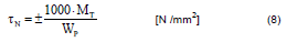
N = Nominal alternating torsional stress referred to the section under consideration to be determined by the formulae (8) [N/mm2],
2 = Transient permissible stresses for speed range to be rapidly passed through [N/mm2].
B. Calculations of Torsional Vibration
1. A torsional vibration analysis covering the torsional vibration stresses to be expected in the main shafting system including its branches is to be submitted to TL for examination. The following data shall be included in the analysis.
Input data:
– Equivalent torsional vibration system: Moments of inertia and inertialess torsional elasticities/stiffnesses for the complete system
– Prime mover: Engine type, rated power, rated speed, cycle number per revolution, design (inline or V-type), number of cylinders, firing order, cylinder diameter, stroke, stroke to connecting rod ratio, oscillating mass of one crank gear, excitation spectrum of engine in the form of tangential coefficients (for new or unconventional types of engines)
– Vibration dampers: Type, damping coefficient, moments of inertia, dynamics stiffness,
– Elastic couplings: Type, damping coefficient, moments of inertia, dynamics stiffness
– Reduction / Power Take Off (PTO) gears: Type, moment of inertia for wheels and pinions, individual gear’s ratios per mesh, effective stiffness
– Shafting: Shaft diameter of crankshafts, intermediate shafts, gear shafts, thrust shafts and propeller shafts,
– Propeller: Type, diameter, number of blades, pitch and expanded area ratio, moment of inertia in air moment of inertia of entrained water (for zero and full pitch for controllable pitch propeller, CPP)
Output data / Results:
– Natural frequencies : With their relevant vibration forms (modes)
– Forced vibratory loads (torques or stresses) : Calculated torques/stresses during torsional vibration movement in all essential elements of the system with particular reference to clearly defined resonance speeds for the whole operating speed range. The results shall include the synthesized values (vectorial sum over all harmonics) for the torques/stresses.
2. The calculations are to be performed both for normal operation (uniform pressure distribution over all cylinders or small deviations in the pressure distribution, e.g. ±5%) and misfiring operation (one cylinder without ignition, compression of the cylinder still existing).
3. Where the installation allows various operation modes, the torsional vibration characteristics are to be investigated for all possible modes, e.g. in installations fitted with controllable pitch propellers for zero and full pitch, with power take off gear integrated in the main gear or at the forward crankshaft end for loaded and idling conditions of the generator unit, with clutches for engaged and disengaged branches.
4. The calculation of torsional vibrations shall also take account of the stresses/torques resulting from the superimposition of several harmonics in so far as this has a bearing on the assessment of the system.
6. Where an electrical machine (e.g. static converter controlled motors) can generate periodic excitation leading to relevant torsional vibration stresses in the system as a whole, this is to be taken into account in the calculation of
the forced torsional vibration. The manufacturer of the electrical machine is responsible for defining the excitation
spectrum in a suitable manner for performing forced torsional vibration calculations.
C. Permissible Stresses for Torsional Vibration
1. Shafting
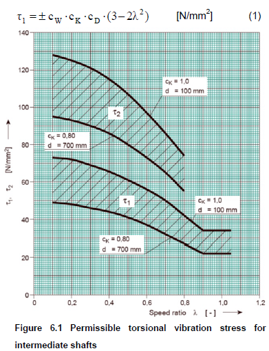
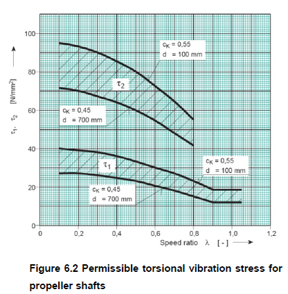
1.1 In no part of the shafting may the alternating torsional vibration stresses exceed the following values of 1 for continuous operation or of 2 under transient conditions. Figures 6.1 and 6.2 indicate the 1 and 2 limits as a reference for intermediate and propeller shafts of common design and for the location deemed to be most severely stressed (cK=0.45 or cK=0.55 for propeller shafts, cK=0.8 and cK=1.0 for intermediate shafts). The limits which depend on the design and the location considered and may in particular cases lie outside the indicated ranges according to Figures 6.1 and 6.2. They are to be determined in accordance with equations (1) ÷ (4) and Table 6.1.
Speed ranges in the ≤ 0.8 area, in which the permissible values of 1 for continuous operation are exceeded shall be crossed through quickly (barred speed ranges for continuous operation), provided that the limit for transient operation 2 is not exceeded.
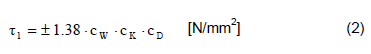
For speed ratio values <0.9 at continuous operation;
For speed ratio values 0.9 < < 1.05 at continuous operation:
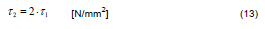
The total stresses at transient operations due to torsional vibration within speed ranges prohibited for continuous running, but which may only be rapidly passed through, shall not exceed the following formulas for intermediate, thrust, propeller shafts and the shafts of the generators driven by the main engine:
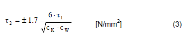
Alternatively, depending on the material and design the following formula may be used instead of (3):
For direct coupled plants, in general, the materials with a tensile strength of Rm ≥ 500 N/mm2 must be used, for geared plants or other plants with low torsional vibration level shafting materials with Rm ≥ 400 N/mm2 may be accepted.
For the purpose of the formulas (1), (2), (3), (4) the tensile strength calculation value applied shall not exceed the mentioned limits in A.4
1.2 In the speed range 0.9 ≤ λ ≤ 1.05 the alternating torques in the shafting system may not exceed 75 % of the mean full-load torque transmitted by the shafting. With the consent of TL, 90 % of the mean torque may be permitted provided that the torque is only transmitted by the frictional connections only or the integrally forged flanges.
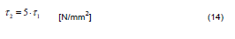
1.3 For the shafts of generators driven by the auxiliary engines, transient stress shall be calculated by formula (14).
1.4 For propeller shafts, the material factor cW is not to be taken as greater than 42.2 (Rm= 600 N/mm2).
1.5 For the controllable pitch propeller systems, the permissible values of 2 within a barred speed range may be exceeded provided that the system is operated at a low pitch and the additional alternating shear stresses remain below the 2 value for λ = 0.6 calculated by formula (3).
Applying this alternative, which is subject to special approval, requires an adequate design case by case.
Especially a fast crossing of barred speed range has to be guaranteed additionally by adequate measures. In such cases an adequate dimensioning of all connections in the shaft system for dynamic torque at resonance speed has to be proven individually.
1.6 For the calculation of the permissible limits of stresses due to torsional vibration, Rm is not to be taken as more than 800 N/mm2 in the case of alloy steel intermediate and thrust shafts, or 600 N/mm2 in the case of carbon and carbon-manganese steel intermediate, thrust and propeller shafts.
1.7 Where the scantlings of coupling bolts and straight shafting differ from the minimum required by the Rules, special consideration will be given.
2. Crankshafts
2.1 Crankshafts applied for engines for ships classed by TL shall be approved on the basis of the Section 2, D. The manufacturer of the engine also applies for approval of a maximal additional (vibratory) shear stress, which is referred to the crank with the highest load due to mean torque and bending forces.
Normally this approved additional shear stress may be applied for first evaluation of the calculated vibratory stresses in the crankshaft via the torsional vibration model. Common values are between 30 and 70 N/mm2 for medium and high speed engines and between 25 and 40 N/mm2 for two stroke engines, but special confirmation of the value considered for judgement by TL is necessary.
For further details see also Section 2, D.
2.2 When the generally approved limit for the vibratory stresses for the crankshaft of the engine as defined under 2.1 is exceeded, special considerations may be applied to define a higher limit for the special investigated case. For this detailed system calculations (combined axial / torsional model) and application of the actual calculated data within the model in accordance with Section 2, D, as quoted under 2.1 are necessary.
Such special considerations, especially the application of combined axial and torsional vibration calculations, may only be considered for direct coupled two stroke engine plants. For such evaluations, in no case the acceptability factor in accordance with the Section 2, D shall be less than 1,15 over the whole speed range.
2.3 Torsional vibration dampers which are aiming to reduce the stresses in the crankshaft shall be suitable for use for diesel engines. TL reserve the right to call for proof of this, compare also F.
Torsional vibration dampers shall be capable of being checked for their performance ability in the assembled condition or shall be capable of being dismounted with reasonable ease for checking purposes. This requirement does not apply for small medium or high speed engines, so far the exchange of the damper is a part of the regular service of the engine and a fixed exchange interval is part of the engine’s crankshaft approval.
2.4 For main engine crankshafts of all the ships except for ice class, and the crankshafts of engines driving generators and other auxiliary machinery for essential services within the speed ratio values 0.9<<1.05, the total stresses due to torsional vibration under conditions of continuous operation shall not exceed the values determined by the following formulas:
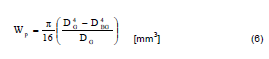
Polar moment of resistance related to the crosssectional area bored journal, WP [mm3] (6)
Nominal alternating torque, MT [Nm] (7)
Nominal alternating torsional stress, N [N /mm2] (8)
Permissible torsional stress as an alternative
or
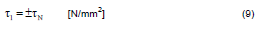
For speed ratio values <0.9 at continuous operation:
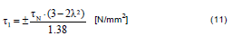
For speed ratio values 0.9<<1.05 at continuous operation:
2.5 The total stress due to torsional vibration within the speed ranges prohibited for continuous operation, but which may only be rapidly passed through, shall not exceed the values determined by the following formulas:
For the crankshafts of main engines
For the crankshafts of engines driving generators or other auxiliary machinery for essential services
2.6 Stress concentration factors of slots
The stress concentration factor (scf) at the end of slots can be determined by means of the following empirical formula
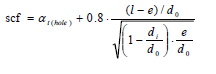
This formula applies to:
– Slots at 120; 180 or 360 degrees apart
– Slots with semicircular ends. A multi-radii slot end can reduce the local stresses, but this is not included in this empirical formula.
– Slots with no edge rounding (except chamfering), as any edge rounding increases the scf slightly.
α t(hole) represents the stress concentration of radial holes ( e = hole diameter) and can be determined as :
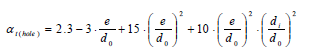
or simplified to t(hole)=2.3 .
3. Gears
3.1 For the case of continuous operation or transient and rapid passage, the alternating torques in any reduction gear stage shall not exceed the permissible values established for the operating conditions by the manufacturer.
3.2 Where the values mentioned under C.3.1 are not available, the alternating torque in any reduction gear step for the case of continuous operation shall satisfy the following conditions:
Within the service speed range 0.9 ≤ λ ≤ 1.05 :
Within the service speed range lower than indicated (<0.9), the permissible value of alternating torque will be specially considered by TL in each case, but, in any case:

For the case of rapid passage, the alternating torque value is subject to special consideration by TL in each case.
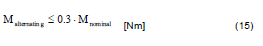
3.3 In the service speed range 0.9 ≤ λ ≤ 1.05, any alternating torque higher than 30% of the mean nominal torque should not occur in any loaded gear’s mesh. Otherwise, the reference values for the permissible bending stresses at the tooth root and for the tooth flank (Hertzian) pressures are to be reduced accordingly. In general, the value for the maximum mean torque transmitted by the gear stage has to be applied for evaluation purposes as the mean nominal torque.
If the gearing is demonstrably designed for a higher power, then, in agreement with TL, 30 % of the design torque of the concerned gear’s mesh concerned may be applied as the load limit.
3.4 The alternating torques in the gear at resonant speeds outside the operational speed range (i.e. when starting up or stopping the engine or within a barred speed range) shall not exceed twice the nominal mean torque for which the gear has been designed.
3.5 Load reversal due to alternating torques is normally permitted only while passing through the lower speed range up to λ ≤ 0.35.
In the special cases such a speed range of λ ≤ 0.35, when the gear hammering is unavoidable, a barred speed range in accordance with E.1 is to be specified.
This requirement does not apply to gear stages which run without load (e.g. the idling stage of a reversing gear or the idling gears of an unloaded shaft-driven generator). These are covered by the provisions in accordance to C.3.6.
3.6 In installations where parts of the gear train run without load, the torsional vibration torque in continuous operation shall not exceed 20 % of the nominal torque in order to avoid unacceptable stresses due to gear hammering. This applies not only to gear stages but also to parts which are particularly subject to torsional vibrations (e.g. multiple-disc clutch mountings). The loaded parts of the gear system are also subject to the provisions of C.3.3.
Higher alternating torques may be approved by TL if proof is submitted to TL that design measures have been taken and the design takes into account these higher loadings see C.3.3.
3.7 In cases where the proposed transmission torque loading on the gear teeth is less than the maximum allowable, special consideration will be given to the acceptance of additional vibratory loading on the gears.
3.8 Where calculations indicate the possibility of torque reversal, the operating speed range is to be determined on the basis of observations during sea trials.
4. Flexible couplings
4.1 Flexible couplings must be designed to withstand the torsional vibration loads which occur in the operation of the ship. In this context, the total load resulting, in accordance with B.4., from the superimposition of several orders is to be taken into account (see also Section 7)
4.2 Flexible couplings must be capable of transmitting for a reasonable time the increased alternating torques which occurs under abnormal operating conditions in accordance with B.2. A reasonable time is, in general, the time consumed until the misfiring operation is detected and the propulsion plant is transferred to a safe operating condition.
Speed ranges within which, under abnormal operating conditions, the continuous operation is not allowed must be indicated in accordance with E.2.
4.3 For the case of continuous operation or transient and rapid passage, the alternating torque in a coupling, relevant stresses in and temperatures of the flexible component material due to torsional vibration shall not exceed the permissible values established for the operating conditions by the manufacturer.
4.4 Where the values mentioned under C.4.3 are not available, the torque, stress and temperature values permissible for continuous operation or transient and rapid passage shall be determined by the procedures approved by TL.
4.5 Where calculations indicate that the limits recommended by the manufacturer may be exceeded under misfiring conditions, a suitable means is to be provided for detecting and indicating misfiring. Under these circumstances power and/or speed restrictions may be required. Where machinery is non-essential, disconnection of the branch containing the coupling would be an acceptable action in the event of misfiring.
5. Shaft-driven generators
5.1 In installations with generators directly and rigidly coupled to the engine (free crankshaft end) it is necessary to ensure that the accelerations do not exceed the values prescribed by the manufacturer in any part of the generator.
The applicable criterion in such cases is the tangential acceleration, which is the product of the angular acceleration and the effective radius. The angular acceleration is determined by means of forced torsional vibrations calculations and is to be regarded as the synthesized value of all major orders. However, for simplified consideration of excited resonant speeds, the value of the individual harmonics may be used instead for assessment.
5.2 The torsional vibration amplitude (angle) of shaft-driven generators shall normally not exceed an electrical value of 5°. The electrical vibration amplitude is obtained by multiplying the mechanical vibration amplitude by the number of pole pairs.
Whether TL is able to permit higher values depends on the configuration of the ship’s electrical system.
6. Connected Units
6.1 If further units (e.g. power turbines or compressors) are coupled to the main propulsion system with or without the ability to declutch, due attention is to be paid to these units when investigated the torsional vibration loadings.
In the assessment of their dynamic loads, the limits as defined by the respective manufacturers are to be considered in addition to the criteria mentioned in C.1. If these limits are exceeded, the units concerned are to be disengaged or prohibited ranges of operation in accordance with E.1 are to be declared. Disengaging of such units shall generally not lead to substantial overloading of the main system in terms of exceeding the 2 limit for shafting systems, the maximum torque for flexible couplings and so on.
6.2 In especially critical cases, the calculations of forced torsional vibrations, including those for disturbed operation (uncoupled set), as stated in B.1 are to be submitted to TL. In such cases TL reserves the right to stipulate the performance of confirmatory measurements (compare. D.) including such as related to disturbed operation.
E. Prohibited Ranges of Operation
1. Operating ranges, which because of the magnitude of the torsional vibration stresses and/or torques, may only be passed through quickly (transient operation), are to be indicated as prohibited ranges of operation by red marks on the tachometer or in some other suitable manner at the operating station.
In normal operation the speed range λ ≥ 0.8 is to be kept free of prohibited ranges of operation.
In specifying prohibited ranges of operation, it has to be observed that the navigating and manoeuvring functions are not severely restricted. The width of the barred speed range is to be selected in a way that the stresses in the shafting do not exceed the permissible τ1 limit for continuous operation with an adequate allowance considering the inaccuracies of the tachometers and the speed setting devices. For geared plants the barred speed ranges, if any, mostly refer to the gear meshes and elastic couplings and are to be determined in the same way with reference to the permissible vibratory torques or permissible power loss for these components (see corresponding paragraphs C.4 and C.5)
2. Measures necessary to avoid overloading the propulsion plant under abnormal operating conditions are to be displayed on an instruction plates to be affixed to all operating stations from which the plant can be controlled.
3. Where the shaft stresses or torques in any components or temperature of the rubber components of flexible coupling arising due to the torsional vibration, exceed the relevant permissible values for continuous running, the restricted speed ranges are assigned.
4. No restricted ranges are permitted for the following speeds:
– In a range of 0.7 for ice-class ships,
– In a range of 0.8 for all ship except for iceclass,
– In the range of 0.9 1.05 for diesel generators and other auxiliary diesel machineries in essential services Where the main diesel generators of ships with electric propulsion plants are concerned, all the fixed speed values corresponding to the specified conditions of partial loading shall alternatively be adopted for no.
5. If all the other methods of decreasing the stresses (or torques) due to the torsional vibration are proven to be ineffective, a vibration damper or a vibration absorber (detuners) or an antivibrator may be mounted where the values of permissible torsion stress are exceed or undesirable as mentioned in C.
The use of dampers or absorbers to limit vibratory stress due to resonances which occur within the range between 0.85 9 1.05 are to be considered. If fitted, these should be of a type which makes adequate provision for dissipation of heat. Where necessary, performance monitoring may be required 6. Restricted speed ranges in one-cylinder misfiring conditions on ships with single engine propulsion are to enable safe navigation whereby sufficient propulsion power is available to maintain control of the ship.
7. There are normally to be no restricted speed ranges imposed above a speed ratio of = 0.8 under normal operating conditions.
F. Auxiliary Machineries
1. General
For the ship’s safety and operation, essential auxiliary machineries such as diesel generators and bow thrusters must be designed in a way that the operating speed range is free of unacceptable stresses due to torsional vibrations in accordance with item C.
2. Generators
2.1 For diesel generator sets with a mechanical output of more than 150 kW torsional vibration calculations must be submitted to TL for approval. The investigations must include natural frequencies as well as forced vibration calculations. The speed range 90% to 105% of the nominal speed shall be investigated under full load conditions (nominal excitation).
2.2 For rigidly coupled generators (without elastic coupling) the vibratory torque in the input part of the generator’s shaft must not exceed 250% of the nominal torque. For the purposes of this requirement, nominal torque is the torque which can be calculated by applying the actual data of the diesel engine (nominal output / nominal speed).
Compliance of the limit of 250% for the nominal torque within a nominal speed range of 90% to 105% shall be proven. The calculation for this speed range should be carried out by utilising the excitation corresponding to the nominal torque as defined above.
Exceeding the limit of 250% for the nominal torque may be considered in exceptional cases, provided that the generator’s manufacturer has designed the generator for a higher dynamical torque. But also in such cases a highest value of 300 % of the actual nominal torque of the gen-set as defined above must not be exceeded.
3. Bow Thrusters
3.1 For bow thrusters as well as for further essential auxiliary machinery driven by a diesel engine with a mechanical output higher than 150 kW, natural as well as forced torsional vibration calculations shall be submitted to TL for approval. The torsional vibration calculations must be focused onto the actual load profile of the set.
3.2 For bow thrusters as well as for further essential auxiliary machinery driven by electrical motor the supplier must check that relevant excitation forces (i.e. propeller blade frequency or similar) may not lead to unacceptable torsional vibration loadings within the set. In special cases TL may require the submission of corresponding calculations.
AXIAL VIBRATION
Machinery, Ch 4 Sec 5
The designer or the builder is to evaluate the shafting system to ensure that axial vibration characteristics in association with diesel engine or propeller blade-rate frequency forces will not result in deleterious effects throughout the engine operating speed range, with consideration also given to the possibility of the coupling of torsional and axial vibration, unless experience with similar shafting system installations makes it unnecessary. The axial vibrations may be controlled by axial vibration detuners to change the natural frequency of the system or by axial vibration dampers to limit the amplitude of axial vibrations to an acceptable level.
When on the basis of axial vibration calculations the designer or builder proposed to provide barred speed ranges within the engine operating speed range, the calculations are to be submitted for information. The barred speed ranges due to axial vibrations are to be verified and established by measurement.
LATERAL VIBRATION
Machinery, Sec 5
The designer or the builder is to evaluate the shafting system to ensure that the amplitudes of lateral (whirling) vibration are of acceptable magnitude throughout the engine operating speed range, unless experience with similar shafting system installations makes it unnecessary.
When on the basis of lateral vibration calculations, the designer or builder proposed to provide barred speed ranges within the engine operating speed range, the calculations are to be submitted for information. The barred speed ranges due to lateral vibration are to be verified and established by measurement.