Y. A. Batrak, Intellectual Maritime Technologies, Ukraine
SUMMARY
There are three main problems for engineers specializing in propulsion train calculations, which include shaft alignment, whirling vibration, bending vibration, axial and torsional vibration calculations. The first problem is a lack of a single shaft model to perform all types of shaft related calculations. Oftentimes separate software with different data models for shaft alignment and for each type of vibration is used. The second problem is inability to analyse different operating states of propulsion shafting in one click. The User is forced to manage and maintain many files to achieve a final solution. The third problem is a substantial disparity between modern knowledge in propulsion train domain and capabilities of the software in use. The above-stated reasons provided a starting point for development of a multi-project, multi-state, FEM-based propulsion train calculation package which integrates all types of engineering applications in the single CAE package named ShaftDesigner and closes the gap between theory and practice.
1. INTRODUCTION
Numerous of in-house and commercially delivered programs are currently used for evaluating propulsion shafting properties, including vibration characteristics and alignment parameters.
Calculations involving shafts are generally based on separate software for shaft alignment and for each type of vibration which therewith supplied by different vendors. In such cases, the model creation for each new alignment or vibration calculation takes up considerable time – especially when several variants of propulsion train design are under development. The amount of data files and necessity of permanent data conversion makes the design process extremely taxing and slow.
Intended to support propulsion shafting designers, shipbuilders/repairers and operators, the new software package integrates all the following FEM-based engineering applications:
- shaft alignment
- whirling vibration
- bending (lateral) vibration
- axial vibration
- torsional vibration
- coupled torsional and axial vibration.
To be useful in practice, the software takes into account the requirements of leading classification societies regarding input and output information for all applications, and is reportedly suitable for the different stages of a ship’s life cycle.
A lot of papers dealing with propulsion shaft calculations have been published in recent decades. They reflect the results of particular scientific research, authors’ experience and their ability to calculate some shaft properties but there was no software that absorbs and integrate all the achievements and findings of scientific thought in one package.
2. BASIC ASSUMPTIONS
New software is a multi-project, multi-state, FEM-based propulsion system calculation package which integrates all types of engineering applications. Logical structure of the software is shown in Fig. 1.
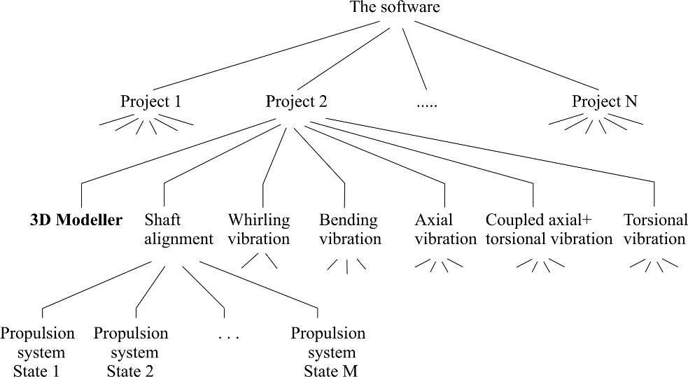
Figure 1: Logical structure of the software
The 3D Modeller is a basic application. It enables a design of a complex propulsion system, comprising several propulsion trains, gearboxes and engines. The 3D Modeller provides a set of tools to implement different approaches to Base Model creation for every situation.
Each train of the Base Model can be subjected to any kind of engineering calculations and in some cases the complete installation can be addressed.
Allowing special features of a given calculation to be taken into account, each application extends the Base Model to so-called Application Model.
The first Application Model for every application is automatically inherited from the Base Model after the the application is started. Subsequent Application Models can be copied from the first and suitably edited by user. Software model hierarchy is shown in Fig 2.
To simulate different states of the propulsion system, (alignment or operational) the user can define a set of Application Models for the trains involved. These models may differ from each other by shafting external parameters (for example, bearing thermal growths, hydrodynamic loads on the propeller, hull deflections) or by the states of the shafting connections (coupled or decoupled). The number of Application Models for one shaft train is not limited.
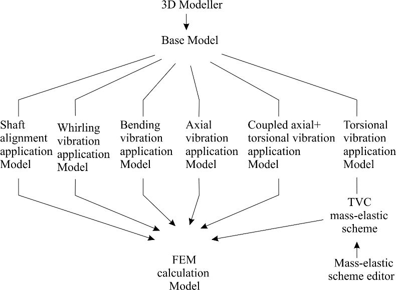
Figure 2: Model hierarchy
The State concept provides a comprehensive analysis of the propulsion shafting via one click. A set of external parameters that defines operating state is termed the Operating Condition. Base Model, Application Models and Calculation Reports are collected in a single Project for management by the Project Manager module.
The propulsion system logical structure is shown in Fig. 3.
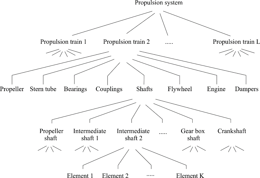
Figure 3: Propulsion system logical structure
Propulsion trains are continuously assembled structures consisting of separate shafts joined by flanged connections or couplings (rigid or flexible) supported by bearings. Each shaft itself is a non-separable unit.
A shaft can be easily divided into Elements, each of which – cylindrical or conical, solid or hollowed – has its own properties. Other objects are easily placed on or inserted into the shafts. Object Inspector manages the properties of these shaft elements and other propulsion shafting objects.
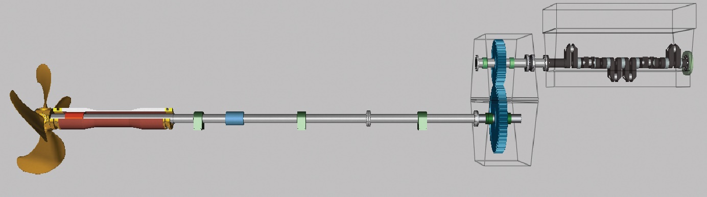
Figure 4: Base Model for geared propulsion system
General view of the Base Model for geared propulsion system is shown in Fig 4.
3. MAIN FUNCTIONAL ADVANTAGES
The software key functional advantages are claimed to be: a 3D graphical processor for propulsion train modelling; integrated environment for all types of engineering calculations; a single Base Model with automatic spreading of changes into all applications; an intuitive graphic user interface based on drag-and-drop technique; a copy/paste function to speed up shafting modelling.
Among other merits undo/redo functions and modelling history list; system repository to store model parts to be used in current or other projects; user’s custom measurement units and fast units converter, colour schemes for implementing corporate standards; easy animation of 3D propulsion train models; no fixed names in the system (each shafting object can be freely named); continuous background calculations of active application; HTML reports can be exported to Microsoft Word document and to XML files.
With the software currently plugging to over 40 modules related to different applications, the user has scope to create the configuration needed and extend it in the future. Special modules for propeller hydrodynamic loads calculation and for hull deflections estimation are supplied too.
Presented software is a useful application at all phases of a ship’s life cycle, from design and construction, to maintenance and repair. Because of the scope of the software, all phases have their specific benefits.
At the design phase an accurate representation of all components of the propulsion train, including engines, gearboxes, bearings and propellers is possible using details about each component. Because of the easy drag and drop function, all the propulsion train components are fast to place, to speed up shaft line modelling.
From an engineering point of view the software provides a useful tool to explore offsets to optimize the position of all propulsion train elements based on acceptance criteria set by the user. This is done in order to guarantee at an early stage a good bearing load distribution and thus safe operation of the shaft line. Because this issue can be identified in the ship’s design phase, possible time-consuming and costly problems can be avoided. Also, at this early stage, it is possible to calculate with the various vibration modules if a certain lay-out has the potential to create harmful vibrations and estimate possible alterations which could be necessary.
If the propulsion train was not modelled with the presented software in the design phase of the ship’s construction, ship builders can reap significant benefits from modelling it at the construction phase before the alignment of the shaft takes place. Where designers can benefit from the fast modelling capabilities of the drag and drop function, ship builders profit from the fact that exact measurements can be easily entered into the software, automatically updating the model every time a new entry is made. The software provides the data for various shaft alignment techniques including jack-load, laser alignment and strain gauge alignment which can be used at various stages of the shaft lines installation.
For maintenance and repair purposes creating a model of the shaft line is a good way to start the job. By subsequently calculating the alignment and vibrations of the shaft, it is possible to detect issues at an early stage that could be influencing the state of the shaft line’s components. Stress points of bearings can for instance be recognized and thus can be checked for wear on board, avoiding costly ship down time in case of failure. Also, using the software it is very easy to verify shaft alignment as condition monitoring after a ship is grounded or after another incident, and evaluate acceptability of alignment changes. It is very important that any dismantling of the propulsion train for this evaluation is not required because of the powerful reversed calculation function.
4. SHAFT ALIGNMENT MODULE
The software provides four different approaches for bearing modeling in shaft alignment calculation: commonly used pointwise support, bilateteral pointwise, ring and cylindrical support with a clearance, Fig 5.
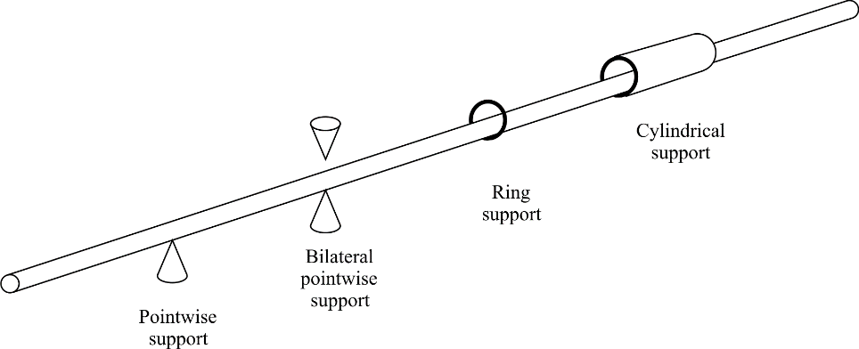
Figure 5: Different approaches for bearing modelling in shaft alignment calculation
Bearings can be set as absolutely stiff supports as well as elastic supports.
A shaft alignment application has the tools for calculating spatial locations of propulsion trains bearings relative to a fixed reference line, securing safe operation of the propulsion train under all specified operating conditions. This means that calculated spatial location of bearing would never result in violation of any specified acceptance criteria of any specified operating condition.
Spatial locations of the bearing are defined by vertical and horizontal bearing offsets and by the angles between the reference line and bearing axis. Ring support and cylindrical support bearing models provides proper boundary conditions for shaft when coupled vertical and horizontal shaft bending are calculated. In these cases and in the case of bilateral pointwise support shaft skipping is taken into account. Shaft skipping phenomenon is clear from the Fig. 6.
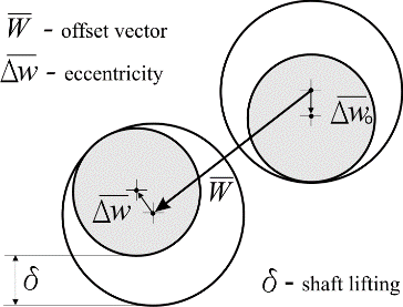
Figure 6: Shaft skipping
There are two types of reference lines in the software: absolute and relative. By default, bearing offsets are related to the absolute base reference line, which coincides with the shaft centerline on the drawing. Any other line can be set as an absolute reference line as well. The relative reference line is one permanently attached to a specified pair of bearings. A user can easily define several reference lines and easily switch between them.
Above mentioned acceptance criteria are the set of emergency limitations assigned to certain parameters of the propulsion train object in a certain application model state.
These limitations originate from classification society requirements or the technical specifications of materials and equipment from manufacturers.
To specify the shaft alignment acceptance criteria in a certain state, the designer should set the permissible values limits using object Inspector and then activate acceptance criteria in options window. Permissible limits can be set for bearing loads, loads on the engine flange, the parameters of special check points and other values. If the bearing axes spatial locations result in violation of the specified acceptance criteria and are not acceptable, the calculation report will contain detailed information on the violations.
Four types of shaft alignment calculations are facilitated by the software: direct and optimal calculations, reverse calculations, and strain gauge alignment calculations.
The reports generated by direct and optimal calculations contain full information on the shafting bending parameters, bush pressure distribution and safe alignment tolerance. Manually inputted bearing offset values are used for all direct calculations. Optimal calculations differ from the direct with the special procedure for evaluation of optimal bearing offsets.
A calculation of the bush pressure distribution defines the realistic position of the bearing reaction point. The static contact pressure and dynamic lubrication pressure diagrams Fig.7, gives the details of the bush loading in operating conditions.
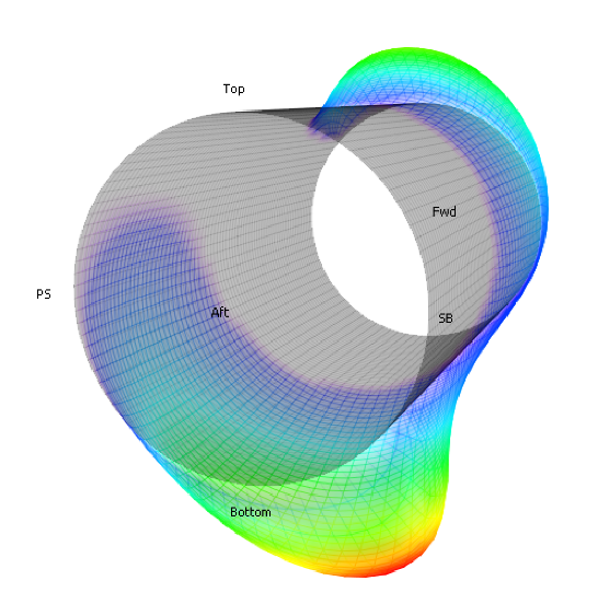
Figure 7: Dynamic lubrication pressure diagram
In executing shaft alignment procedures on board, it is important to know the permissible ranges of measured parameters. The safe alignment tolerance concept is used to calculate these ranges.
Safe alignment tolerance is a half-side of a hypercube placed in allowable offsets hyperspace with a centre in the point that corresponds to the assigned bearing offsets. The tolerance reflects the maximum simultaneous deviations, both positive and negative, from the calculated bearing offsets that do not result in acceptance criteria violation.
The software provides the functions to investigate the hyperspace of allowable offsets and searching for bearing offsets with a maximum tolerance. A safe alignment tolerance is also used for calculation of permissible ranges for other shaft bending parameters.
Reversed calculations are direct alignment calculations fulfilled using bearing offsets, automatically determined from specific measured data such as sags and gaps, bending stress, jack loads and shaft deflections. These calculations are indispensable in aligning propulsion shafting in ship repair projects.
The strain gauge alignment function is intended for onboard application, to calculate bearing adjustments leading to the specified bearing offsets.
Measured bending stress or strain instrumentation readings are used to calculate the bearing adjustments. To facilitate the process of strain gauge alignment the bearing adjustments are visualized with the special diagram, Fig. 8.
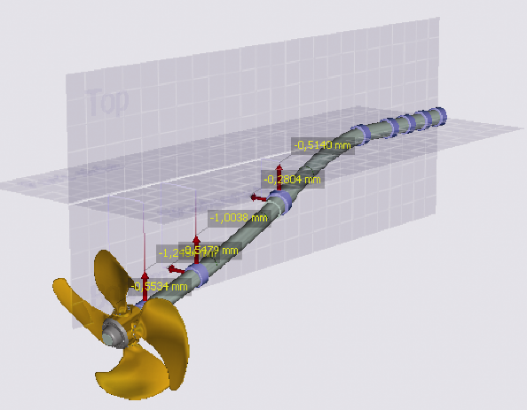
Figure 8: Bearing adjustments diagram
If the legacy jack-up test is planned to check bearing loads the software generate theoretical jack-up test diagram to predict the shaft behaviour during real jack-up test in-situ.
5. SHAFT VIBRATION MODULES
The software provides free and forced vibration calculations. The main results of the free vibration calculation for each type of vibration are the following characteristics: natural frequencies and mode shapes as well as resonance speeds in the form of Campbell diagram and resonance table. Whirling vibration calculation results include the list of critical speeds for forward and backward whirling; excitation order No 1 corresponds to synchronous whirling. Campbell diagram view for whirling vibration is shown in Fig. 9.
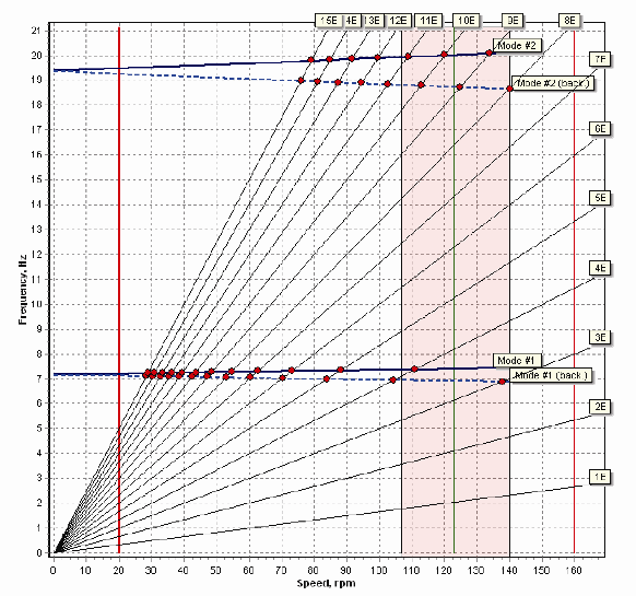
Figure 9: Campbell diagram
Torsional vibration calculations may be performed for a complete propulsion train or its parts, with different states of clutch connections. Torsional vibration application additionally provides special graphics editor, to create a mass-elastic system when the base model is not available.
The software allows the automatically generated parts of such a mass-elastic system to be combined with the systems supplied by engine, gearbox and other rotating machinery manufacturers.
Steady forced vibration calculation can be performed in a frequency domain for most dangerous type of vibration: torsional, axial and coupled axial-torsional. The last is available for directly driven installation only.
The forced vibration can be calculated by two different methods: mode superposition method and full solution method. A lot of possibilities to set excitation and damping parameters for these methods is one of the software advantages that make it flexible and easy to use.
If the propulsion train is diesel engine driven the calculations can be performed for normal operation of the engine as well as for misfiring mode.
To explore forced vibration calculation results special interactive browser is provided. Vibration amplitudes, dynamical forces and stress dependence on shaft rotation speed can be seen in graphic form, Fig. 10.
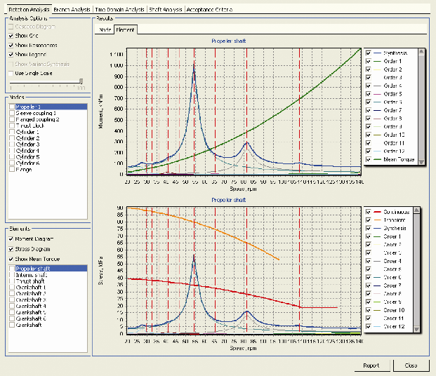
Figure 10: Forced vibration calculation results
The calculation results are compared with the acceptance criteria set by user to see are the criteria satisfied or not. User has the possibility to select separate graphs to be included in calculation report.
The forced vibration calculation results for a single node or element may be presented in time domain form.
6. CONCLUSIONS
The new CAE package for propulsion train calculation is a result of close cooperation of the Intellectual Maritime Technologies and Machine Support BV companies having of many years correspondingly theoretical and practical experience in propulsion shafting domain.
Thanks to the software’s capabilities to perform reversed calculations, the theory and practical findings were cross-validated and guarantee accurate results.
In the development of new software for propulsion train calculations there was a continuous coordination with classification societies and leading OEMs of various components of the propulsion train, in order to meet their needs.
The software is useful for application in each phase of a ship’s life cycle, from design and construction, to maintenance and repair.
Concepts embodied in the presented software open the broad and reliable way for further continual improvement of the software.
As the first step the possibility to import propulsion train 3D models developed with the mechanical CAD systems will be provided.
As an aid for the designers at the early stage special rule-based software for propulsion train automatic synthesis can be developed.
Last but not least a condition monitoring system for propulsion train can be developed on the base of the presented software.
7. AUTHOR BIOGRAPHY
Dr. Yuriy Batrak holds the current position of a consultant at Intellectual Maritime Technologies company. He is responsible for the problems’ statement and for the software mathematic. His previous experience includes developing of ShaftMaster software for shaft alignment calculations, experimental works at the shipyards and lectures on computer science and mathematic at the university.