Lloyd-Register-1916.pdf (1375 downloads)
Rules and Regulations for the Classification of Ships, January 2016
Part 5 Main and Auxiliary Machinery, Chapter 8 Shaft vibration and Alignment
ALIGNMENT
Section 5 Shaft alignment
5.1 General
5.1.1 Shaft alignment calculations are to be carried out for main propulsion shafting rotating at propeller speed, including the crankshaft of direct drive systems or the final reduction gear wheel on geared installations. The Builder is to make available shaft alignment procedures detailing the proposed alignment method and checks for these arrangements.
5.2 Particulars to be submitted for approval – Shaft alignment calculations
5.2.1 Shaft alignment calculations are to be submitted to LR for approval for the following shafting systems:
(a) All geared installations, where the screwshaft has a diameter of 300 mm or greater in way of the aftmost bearing.
(b) All geared installations with multiple input/single output, regardless of shaft diameter.
(c) All direct drive installations which incorporate three or fewer bearings supporting the intermediate and screwshaft aft of the prime mover.
(d) Where prime movers in a direct drive installation or shaftline bearings are installed on resilient mountings.
(e) All systems where the screwshaft has a diameter of 800 mm or greater in way of the aftmost bearing.
5.2.2 The shaft alignment calculations are to take into account the:
(a) thermal displacements of the bearings between cold static and hot dynamic machinery conditions;
(b) buoyancy effect of the propeller immersion due to the ship’s operating draughts;
(c) effect of predicted hull deformations over the range of the ship’s operating draughts, where known;
(d) effect of filling the aft peak ballast tank upon the bearing loads, where known;
(e) gear forces, where appropriate, due to prime-mover engagement on multiple input/single output installations. For multiple input systems, consideration is to be given to each possible combination of inputs;
(f) propeller offset thrust effects;
(g) maximum allowed bearing weardown, for water or grease-lubricated sterntube bearings, and its effect on the bearing loads.
5.2.3 The shaft alignment calculations are to state the:
(a) expected bearing loads at light and normal ballast, fully loaded and any other draughts deemed to be part of the ship’s
operating profile, for the machinery in cold and hot, static and dynamic conditions;
(b) bearing influence coefficients and the deflection, slope, bending moment and shear force along the shaftline;
(c) details of propeller offset thrust;
(d) details of proposed slope-bore of the aftermost sterntube bearing, where applicable;
(e) manufacturer’s specified limits for bending moment and shear force at the shaft couplings of the gearbox/prime movers;
(f) estimated bearing weardown rates for water or grease-lubricated sterntube bearings;
(g) expected hull deformation effects and their origin, viz. whether finite element calculations or measured results from sister or similar ships have been used;
(h) anticipated thermal rise of prime movers and gearing units between cold static and hot running conditions; and
(i) manufacturer’s allowable bearing loads.
5.3 Shaft alignment procedures
5.3.1 A shaft alignment procedure is to be made available for review and for the information of the attending surveyors for all main propulsion installations detailing, as a minimum,
(a) expected bearing loads at light and normal ballast, fully loaded and any other draughts deemed to be part of the ship’s operating profile, for the machinery in cold and hot, static and dynamic conditions;
(b) maximum permissible loads for the proposed bearing designs;
(c) design bearing offsets from the straight line;
(d) design gaps and sags;
(e) location and loads for the temporary shaft supports;
(f) expected relative slope of the shaft and the bearing in the aftermost sterntube bearing;
(g) details of slope-bore of the aftermost sterntube bearing, where applied;
(h) proposed bearing load measurement technique and its estimated accuracy;
(i) jack correction factors for each bearing where the bearing load is measured using a specified jacking technique;
(j) proposed shaft alignment acceptance criteria, including the tolerances; and
(k) flexible coupling alignment criteria.
5.4 Design and installation criteria
5.4.1 For main propulsion installations, the shafting is to be aligned to give, in all conditions of ship loading and machinery operation, bearing load distribution satisfying the requirements of Pt 5, Ch 8, 5.4 Design and installation criteria 5.4.2.
5.4.2 Design and installation of the shafting is to satisfy the following criteria:
(a) The Builder is to position the bearings and construct the bearing seatings to minimise the effects of hull deflections under any of the ship’s operating conditions with the aim of optimising the bearing load distribution.
(b) Relative slope between the propeller shaft and the aftermost sterntube bearing is, in general, not to exceed 3 x 10⁻⁴ rad in the static condition..
(c) Sterntube bearing loads are to satisfy the requirements of Ch 6,3.12.
(d) Evidence is to be provided to LR demonstrating that bearings of synthetic material have been verified as being within the tolerance stated by the bearing manufacturer for diameter, ovality, and straightness after installation.
(e) Bearings of synthetic material are to be verified as being within tolerance for ovalilty and straightness, circumferentially and longitudinally, after installation.
(f) The sterntube forward bearing static load is to be sufficient to prevent unloading in all static and dynamic operating
conditions, including the transient conditions experienced during manoeuvring turns and during operation in heavy weather.
(g) Intermediate shaft bearings’ loads are not to exceed 80 per cent of the bearing manufacturer’s allowable maximum load, for plain journal bearings, based on the bearing projected area.
(h) Equipment manufacturer’s bearing loads are to be within the manufacturer’s specified limits, i.e. prime movers, gearing.
(i) Resulting shear forces and bending moments are to meet the equipment manufacturer’s specified coupling conditions.
(j) The manufacturer’s radial, axial and angular alignment limits for the flexible couplings are to be maintained.
Chapter 6
3.12 Sternbushes
3.12.1 The length of the bearing in the sternbush next to and supporting the propeller is to be as follows:
(a) For water lubricated bearings which are lined with lignum vitae, rubber composition or staves of approved plastics material, the length is to be not less than four times the diameter required for the screwshaft under the liner.
(b) For water lubricated bearings lined with two or more circumferentially spaced sectors of an approved plastics material, in which it can be shown that the sectors operate on hydrodynamic principles, the length of the bearing is to be such that the nominal bearing pressure will not exceed 5,5 bar (5,6 kgf/cm2). The length of the bearing is to be not less than twice its diameter.
(c) For oil lubricated bearings of synthetic material the flow of lubricant is to be such that overheating, under normal operating conditions, cannot occur. The acceptable nominal bearing pressure will be considered upon application and is to be supported by the results of an agreed test programme. In general, the length of the bearing is not to be less than 2,0 times the rule diameter of the shaft in way of the bearing.
(d) For bearings which are white-metal lined, oil lubricated and provided with an approved type of oil sealing gland, the length of the bearing is to be approximately twice the diameter required for the screwshaft and is to be such that the nominal bearing pressure will not exceed 8,0 bar (8,1 kgf/cm2). The length of the bearing is to be not less than 1,5 times its diameter.
(e) For bearings of cast iron and bronze which are oil lubricated and fitted with an approved oil sealing gland, the length of the bearing is, in general, to be not less than four times the diameter required for the screwshaft.
(f) For bearings which are grease lubricated, the length of the bearing is to be not less than four times the diameter required for the screwshaft.
TORSIONAL VIBRATION
Section 2 Torsional vibration
2.1 General
2.1.1 In addition to the shafting complying with the requirements of Pt 5, Ch 1 General Requirements for the Design and Construction of Machinery to Pt 5, Ch 7 Propellers and Pt 5, Ch 20 Azimuth Thrusters (where applicable), approval is also dependent on the torsional vibration characteristics of the complete shafting system(s) being found satisfactory.
2.1.2 Further to the Scope of this Chapter, the requirements of this Section are applicable:
(a) to ships that are required to comply with the SOLAS – International Convention for the Safety of Life at Sea , as amended, (SOLAS); and
(b) for all other ships where any one main engine has a power output exceeding 500 kW.
2.2 Particulars to be submitted
2.2.1 Torsional vibration calculations, showing the mass elastic values, associated natural frequencies and an analysis of the vibratory torques and stresses for the full dynamic system.
2.2.2 Particulars of the division of power and utilisation, throughout the speed range, for turbines, multi-engine or other combined power installations, and those with power take-off systems. For multi-engined installations, special considerations associated with the possible variations in the mode of operation and phasing of engines.
2.2.3 Enginebuilder’s harmonic torque data used in the torsional vibration calculations, see Pt 5, Ch 8, 2.3 Scope of
calculations 2.3.3.
2.2.4 Details of operating conditions encountered in service for prolonged periods, e.g. idling speed, range of trawling
revolutions per minute, combinator characteristics for installations equipped with controllable pitch propellers.
2.2.5 Details, obtained from the manufacturers, of the principal characteristics of machinery components such as dampers and couplings, confirming their capability to withstand the effects of vibratory loading including, where appropriate, heat dissipation. Evidence that the data which is used to represent the characteristics of components, which has been quoted from other sources, is supported by a programme of physical measurement and control.
2.2.6 Where installations include electric motors, generators or non-integral pumps, drawings showing the principal dimensions of the shaft, together with manufacturer’s estimates of mass moment of inertia for the rotating parts.
2.2.7 Details of vibration or performance monitoring proposals where required.
2.3 Scope of calculations
2.3.1 Calculations are to be carried out, by recognised techniques, for the full dynamic system formed by the oil engines, turbines, motors, generators, flexible couplings, gearing, shafting and propeller, where applicable, including all branches.
2.3.2 Calculations are to give due consideration to the potential deviation in values used to represent component
characteristics due to manufacturing/service variability.
2.3.3 The calculations carried out on oil engine systems are to be based on the Enginebuilders’ harmonic torque data. The calculations are to take account of the effects of engine malfunctions commonly experienced in service, such as a cylinder not firing (i.e. no injection but with compression) giving rise to the highest torsional vibration stresses in the shafting. Calculations are also to take account of a degree of imbalance between cylinders, which is characteristic of the normal operation of an engine under service conditions.
2.3.4 Whilst limits for torsional vibration stress in crankshafts are no longer stated explicitly, calculations are to include estimates of crankshaft stress at all designated operating/service speeds, as well as at any major critical speed.
2.3.5 Calculations are to take into account the possible effects of excitation from propeller rotation. Where the system shows some sensitivity to this phenomenon, propeller excitation data for the installation should be used as a basis for calculation, and submitted.
2.3.6 Where the torsional stiffness of flexible couplings varies with torque, frequency or speed, calculations should be representative of the appropriate range of effective dynamic stiffness.
2.4 Symbols and definitions
2.4.1 The symbols used in this Section are defined as follows:
d = minimum diameter of shaft considered, in mm
di = diameter of internal bore, in mm
k = the factor used in determining minimum shaft diameter, defined in Pt 5, Ch 6, 3.1 Intermediate shafts 3.1.1 and Pt 5, Ch 6, 3.5 Screwshafts and tube shafts 3.5.1
r = ratio N/N s or N c/N s whichever is applicable
C d = a size factor defined as 0,35 + 0,93d –0,2
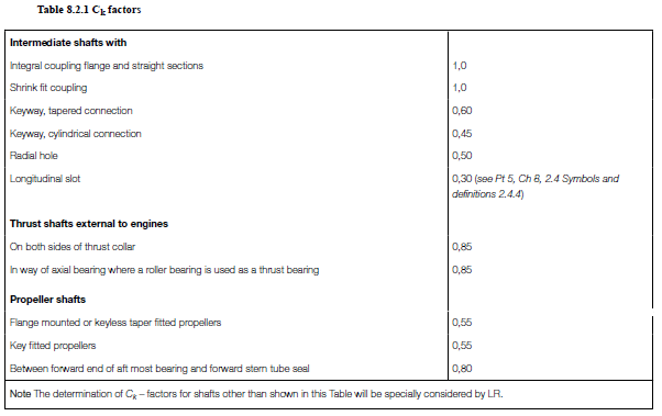
C k = a factor for different shaft design features, see Table 8.2.1 Ck factors
N = engine speed, in rev/min
N c = critical speed, in rev/min
N s = maximum continuous engine speed, in rev/min, or, in the case of constant speed generating sets, the full load speed, in rev/min
Q s = rated full load mean torque
σu = specified minimum tensile strength of the shaft material, in N/mm2
τc = permissible stress due to torsional vibrations for continuous operation, in N/mm2
τt = permissible stress due to torsional vibrations for transient operation, in N/mm2
e = slot width, in mm
l = slot length, in mm.
2.4.2 Alternating torsional vibration stresses are to be based on half-range amplitudes of stress resulting from the alternating torque (which is superimposed on the mean torque) representing the synthesis of all harmonic orders present.
2.4.3 All vibration stress limits relate to the synthesis or measurement of total nominal torsional stress and are to be based on the plain section of the shafting neglecting stress raisers.
2.4.4 For a longitudinal slot Ck = 0,3 is applicable within the dimension limitations given in Pt 5, Ch 6, 3.1 Intermediate shafts
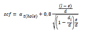
3.1.6. If the slot dimensions are outside these limitations, or if the use of another Ck is desired, the actual stress concentration factor (scf) is to be documented or determined from Pt 5, Ch 8, 2.4 Symbols and definitions 2.4.5 or by direct application of FE calculation , in which case:

Note that the scf is defined as the ratio between the maximum local principal stress and 3 times the nominal torsional stress (determined for the bored shaft without slots).
2.4.5 Stress concentration factor of slots. The stress concentration factor (scf) at the ends of slots can be determined by means of the following empirical formulae:
This formula applies to:
• Slots at 120 or 180 or 360 degrees apart.
• Slots with semicircular ends. A multi-radii slot end can reduce the local stresses, but this is not included in this empirical formula.
• Slots with no edge rounding (except chamfering), as any edge rounding increases the scf slightly.
αt(hole) represents the stress concentration of radial holes and can be determined as :

where , in this context, e = hole diameter, in mm (this is independent of slot width) or simplified to αt(hole) = 2,3.
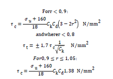
2.5 Limiting stress in propulsion shafting
2.5.1 The following stress limits apply to intermediate shafts, thrust shafts and to screwshafts fully protected from sea water. For screwshafts, the limits apply to the minimum sections of the portions of the screwshaft as defined in Pt 5, Ch 6, 3.5 Screwshafts and tube shafts.
2.5.2 In the case of unprotected screwshafts, special consideration will be given.
2.5.3 In no part of the propulsion shafting system may the alternating torsional vibration stresses exceed the values of τc for continuous operation, and τt for transient running, given by the following formulae:
2.5.4 In general, the tensile strength of the steel used is to comply with the requirements of Pt 5, Ch 6, 2 Materials. For the calculation of the permissible limits of stresses due to torsional vibration, σu is not to be taken as more than 800 N/mm2 in the case of alloy steel intermediate shafts, or 600 N/mm2 in the case of carbon and carbon-manganese steel intermediate, thrust and propeller shafts.
2.5.5 Where the scantlings of coupling bolts and straight shafting differ from the minimum required by the Rules, special consideration will be given.
2.6 Generator sets
2.6.1 Natural frequencies of the complete set are to be sufficiently removed from the firing impulse frequency at the full load speed, particularly where flexible couplings are interposed between the engine and generator.
2.6.2 Within the speed limits of 0,95N s and 1,05N s the vibration stresses in the transmission shafting are not to exceed the values given by the following formula:

2.6.3 Vibration stresses in the transmission shafting due to critical speeds which have to be passed through in starting and stopping, are not to exceed the values given by the following formula:

2.6.4 The amplitudes of the total vibratory inertia torques imposed on the generator rotors are to be limited to 2,0Q s in general, or to 2,5Q s for close-coupled revolving field alternating current generators, over the speed range from 0,95N s to 1,05Ns. Below 0,95N s the amplitudes are to be limited to 6,0Q s. Where two or more generators are driven from one engine, each generator is to be considered separately in relation to its own rated torque.
2.6.5 The rotor shaft and structure are to be designed to withstand these magnitudes of vibratory torque. Where it can be
shown that they are capable of withstanding a higher vibratory torque, special consideration will be given.
2.6.6 In addition to withstanding the vibratory conditions over the speed range from 0,95N s to 1,05N s, flexible couplings, if fitted, are to be capable of withstanding the vibratory torques and twists arising from transient criticals and short-circuit currents.
2.6.7 In the case of alternating current generators, resultant vibratory amplitudes at the rotor are not to exceed 3,5 electrical degrees under both full load working conditions and the malfunction condition mentioned in Pt 5, Ch 8, 2.3 Scope of calculations 2.3.3.
2.7 Other auxiliary machinery systems
2.7.1 The relevant requirements of Pt 5, Ch 8, 2.6 Generator sets 2.6.1, Pt 5, Ch 8, 2.6 Generator sets 2.6.2 and Pt 5, Ch 8,
2.6 Generator sets 2.6.3 are also applicable to other machinery installations such as pumps or compressors with the speed limits being taken as 0.95N s to 1.10N s.
2.8 Other machinery components
2.8.1 Torsional vibration dampers. The use of dampers or detuners to limit vibratory stress due to resonances which occur within the range between 0,85N s and 1,05N s are to be considered. If fitted, these should be of a type which makes adequate provision for dissipation of heat. Where necessary, performance monitoring may be required.
2.8.2 Flexible couplings:
(a) Flexible couplings included in an installation are to be capable of transmitting the mean and vibratory loads without exceeding the makers’ recommended limits for angular amplitude or heat dissipation.
(b) Where calculations indicate that the limits recommended by the manufacturer may be exceeded under misfiring conditions, a suitable means is to be provided for detecting and indicating misfiring. Under these circumstances power and/or speed restrictions may be required. Where machinery is non-essential, disconnection of the branch containing the coupling would be an acceptable action in the event of misfiring.
2.8.3 Gearing:
(a) The torsional vibration characteristics are to comply with the requirements of Pt 5, Ch 8, 2.3 Scope of calculations. The sum of the mean and of the vibratory torque should not exceed four-thirds of the full transmission torque, at MCR, throughout the speed range. In cases where the proposed transmission torque loading on the gear teeth is less than the maximum allowable, special consideration will be given to the acceptance of additional vibratory loading on the gears.
(b) Where calculations indicate the possibility of torque reversal, the operating speed range is to be determined on the basis of observations during sea trials.
2.9 Measurements
2.9.1 Where calculations indicate that the limits for torsional vibration within the range of working speeds are exceeded, measurements, using an appropriate technique, may be taken from the machinery installation for the purpose of approval of torsional vibration characteristics, or determining the need for restricted speed ranges, and the confirmation of their limits.
2.9.2 Where differences between calculated and measured levels of stress, torque or angular amplitude arise, the stress limits are to be applied to the stresses measured on the completed installation.
2.9.3 The method of measurement is to be appropriate to the machinery components and the parameters which are of concern. Where shaft stresses have been estimated from angular amplitude measurements, and are found to be close to limiting stresses as defined in Pt 5, Ch 8, 2.5 Limiting stress in propulsion shafting, strain gauge techniques may be required. When measurements are required, detailed proposals are to be submitted.
2.10 Vibration monitoring
2.10.1 Where calculations and/or measurements have indicated the possibility of excessive vibratory stresses, torques or angular amplitudes in the event of a malfunction, vibration or performance monitoring, directly or indirectly, may be required.
2.11 Restricted speed and/or power ranges
2.11.1 Restricted speed and/or power ranges will be imposed to cover all speeds where the stresses exceed the limiting values, τc, for continuous running , including one cylinder misfiring conditions if intended to be continuously operated under such conditions. For controllable pitch propellers with the possibility of individual pitch and speed control, both full and zero pitch conditions are to be considered. Similar restrictions will be imposed, or other protective measures required to be taken, where vibratory torques or amplitudes are considered to be excessive for particular machinery items. At each end of the restricted speed range the engine is to be stable in operation.
2.11.2 The restricted speed range is to take account of the tachometer speed tolerances at the barred speeds.
2.11.3 Critical responses which give rise to speed restrictions are to be arranged sufficiently removed from the maximum revolutions per minute to ensure that, in general, at r = 0,8 the stress due to the upper flank does not exceed τc.
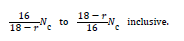
2.11.4 Provided that the stress amplitudes due to a torsional critical response at the borders of the barred speed range are less than τc under normal and stable operating conditions the speed restriction derived from the following formula may be applied:
2.11.5 Where calculated vibration stresses due to criticals below 0,8N s marginally exceed τc or where the critical speeds are sharply tuned, the range of revolutions restricted for continuous operation may be reduced.
2.11.6 In cases where the resonance curve of a critical speed has been derived from measurements, the range of revolutions to be avoided for continuous running may be taken as that over which the measured vibration stresses are in excess of τc, having regard to the tachometer accuracy.
2.11.7 Where restricted speed ranges under normal operating conditions are imposed, notice boards are to be fitted at the control stations stating that the engine is not to be run continuously between the speed limits obtained as above, and the engine tachometers are to be marked accordingly.
2.11.8 Where vibration stresses approach the limiting value τt, the range of revolutions restricted for continuous operation may be extended. The notice boards are to indicate that this range must be passed through rapidly.
2.11.9 For excessive vibratory torque, stress or amplitude in other components, based on Pt 5, Ch 8, 2.8 Other machinery components 2.8.1 to Pt 5, Ch 8, 2.8 Other machinery components 2.8.3, the limits of any speed/power restriction are to be such as to maintain acceptable levels during continuous operation.
2.11.10 Where the restrictions are imposed for the contingency of an engine malfunction or component failure, the limits are to be entered in the machinery Operating Manual.
2.11.11 Restricted speed ranges in one-cylinder misfiring conditions on ships with single engine propulsion are to enable safe navigation whereby sufficient propulsion power is available to maintain control of the ship.
2.11.12 There are to be no restricted speed ranges imposed above a speed ratio of r = 0,8 under normal operating conditions.
2.12 Tachometer accuracy
2.12.1 Where restricted speed ranges are imposed as a condition of approval, the tachometer accuracy is to be checked against the counter readings, or by equivalent means, in the presence of the Surveyors to verify that it reads correctly within 2 per cent in way of the restricted range of revolutions.
2.13 Governor control
2.13.1 Where there is a significant critical response above and close to the maximum service speed, consideration is to be given to the effect of temporary overspeed.
AXIAL VIBRATION
Section 3 Axial vibration
3.1 General
3.1.1 For all main propulsion shafting systems, the Shipbuilders are to ensure that axial vibration amplitudes are satisfactory throughout the speed range. Where natural frequency calculations indicate significant axial vibration responses, sufficiently wide restricted speed ranges will be imposed. Alternatively, measurements may be used to determine the speed ranges at which amplitudes are excessive for continuous running.
3.2 Particulars to be submitted
3.2.1 The results of calculations, together with recommendations for any speed restrictions found necessary.
3.2.2 Enginebuilder’s recommendation for axial vibration amplitude limits at the non-driving end of the crankshaft or at the thrust collar.
3.2.3 Estimate of flexibility of the thrust bearing and its supporting structure.
3.2.4 The requirement for calculations to be submitted may be waived upon request provided evidence of satisfactory service experience of similar dynamic installations is submitted.
3.3 Calculations
3.3.1 Calculations of axial vibration natural frequency are to be carried out using appropriate techniques, taking into account the effects of flexibility of the thrust bearing, for shaft systems where the propeller is:
(a) Driven directly by a reciprocating internal combustion engine.
(b) Driven via gears, or directly by an electric motor, and where the total length of shaft between propeller and thrust bearing is in excess of 60 times the intermediate shaft diameter.
3.3.2 Where an axial vibration damper is fitted, the calculations are to consider the effect of a malfunction of the damper.
3.3.3 For those systems as defined in Pt 5, Ch 8, 3.3 Calculations 3.3.1 the propeller speed at which the critical frequency occurs may be estimated using the following formula:

Where the results of this method indicate the possibility of an axial vibration resonance in the vicinity of the maximum service speed, calculations using a more accurate method will be required.
3.4 Measurements
3.4.1 Where calculations indicate the possibility of excessive axial vibration amplitudes within the range of working speeds under normal or malfunction conditions, measurements are required to be taken from the shafting system for the purpose of determining the need for restricted speed ranges.
3.5 Restricted speed ranges
3.5.1 The limits of any speed restriction are to be such as to maintain axial amplitudes within recommended levels during continuous operation.
3.5.2 Limits of speed restriction, where required, may be determined by calculation or on the basis of measurement.
3.5.3 Where a speed restriction is imposed for the contingency of a damper malfunction, the speed limits are to be entered in the machinery Operating Manual and regular monitoring of the axial vibration amplitude is required. Details of proposals for monitoring are to be submitted.
3.6 Vibration monitoring
3.6.1 Where a vibration monitoring system is to be specified, details of proposals are to be submitted.
LATERAL VIBRATION
Section 4 Lateral vibration
4.1 General
4.1.1 For all main propulsion shafting systems, the Shipbuilders are to ensure that lateral vibration characteristics are
satisfactory throughout the speed range.
4.2 Particulars to be submitted
4.2.1 Calculations of the lateral vibration characteristics of shafting systems having supports outboard of the hull or
incorporating cardan shafts are to be submitted.
4.3 Calculations
4.3.1 The calculations in Pt 5, Ch 8, 4.2 Particulars to be submitted 4.2.1, taking account of bearing, oil-film (where
applicable) and structural dynamic stiffnesses, are to investigate the excitation frequencies giving rise to all critical speeds which may result in significant amplitudes within the speed range, and are to indicate relative deflections and bending moments throughout the shafting system.
4.3.2 The calculated natural frequencies of the system are to be compared to both the shaft rotational orders and propeller blade passing frequencies. Where cardan shafts are fitted, the shaft second rotational orders are also to be considered.
4.3.3 Requirements for calculations may be waived upon request provided evidence of satisfactory service experience of similar dynamic installations is submitted.
4.4 Measurements
4.4.1 Where calculations indicate the possibility of significant lateral vibration responses within the range of Ѓ} 20 per cent of M.C.R. speed, measurements using an appropriate recognised technique may be required to be taken from the shafting system for the purpose of determining the need for restricted speed ranges.
4.4.2 The method of measurement is to be appropriate to the machinery arrangement and the modes of vibration which are of concern. When measurements are required, detailed proposals are to be submitted in advance.