KOREAN-REGISTER.pdf (652 downloads)
RULES FOR THE CLASSIFICATION OF STEEL SHIPS, 2016
ALIGNMENT
GUIDANCE Pt 5 Ch 1 Sec 2
2. In application to 202. 2 (5) of the Rules, where considered necessary by the Society is the following (1), and shaft alignment calculations are to comply with the following (2) and (3).
(1) Shaft alignment calculations for the following alignment-sensitive types of installations are to be submitted for reference :
(A) Propulsion shafting of the actual propeller shaft diameter not less than 400mm.
(B) Propulsion shafting with reduction gears where the gear wheel is driven by two or more ahead pinions.
(C) Propulsion shafting for which the propeller shaft bearings are to be slope-boring.
(D) Propulsion shafting for which the bearings in shafting are to be slope-alignment
(2) The alignment calculations are to include bearing reactions, shear forces and bending moments along the shafting, slope boring details (if applicable) and detailed description of alignment procedure.
(3) The alignment calculations are to take account of thermal effects, and to be performed for cold and hot conditions of the shafting.
Pt 5, Ch 3
206. Stern tube bearing and sealing device
1. The length of stern bearing in the stern tube or of strut bearing supporting the weight of propeller is to comply with the following requirements.
(1) The bearings are to be type approved by the Society in their materials, construction and lubricating arrangements when rubber or synthetic materials are used.
(2) For sea water lubricated bearings of lignum vitae, rubber or synthetic materials, the length of the bearing is to be not less than 4 times the required diameter of the shaft in way of the bearing. However when rubber or synthetic materials are used, where the material has been proven satisfaction of society through testing and operating experience, consideration may be given to an increased bearing pressure or a lessened bearing length. In this case, the length of the bearing is to be not less than 2 times the required diameter of the shaft in way of the bearing.
(3) For oil lubricated bearings of white metal or synthetic materials, the length of the bearing is to be not less than 2 times the required diameter of the shaft in way of the bearing. The length of the bearing may be less provided the nominal bearing pressure is not more than 0.8 MPa as determined by static bearing reaction calculation taking into account shaft and propeller weight which is deemed to be exerted solely on the aft bearing divided by the projected area of the shaft. For oil lubricated bearings of synthetic materials, the length of the bearing may be less provided the nominal bearing pressure is not more than 0.6 MPa as determined by static bearing reaction calculation taking into account shaft and propeller weight which is deemed to be exerted solely on the aft bearing divided by the projected area of the shaft. However, the minimum length is to be not less than 1.5 times the actual diameter. 【See Guidance】
Pt 5 Ch 3
206. Stern tube bearing and sealing devices
In application to 206. 1. (3) of the Rules, where the length of oil lubricated bearings is less than 2 times the required calculation diameter of the propeller shaft in way of the bearing, the following are to be satisfied with.
(1) Improvement in condition of bearing loads The relative contact condition between propeller shaft and its bearing in the longitudinal direction is to be improved by employing the slope alignment (including the slope boring) and uniform distribution of bearing loads are to be ensured. For approval of the above, an slop alignment calculation sheet (bending moment, bending stress bearing pressure, bearing load, amount of deflection, angle of inclination, etc.) satisfying the following, and installation instruction is to be submitted.
(A) Alignment calculation only dealing with the static external force may be accepted (the review for shaft alignment variation due to dynamic force such as variation of bending moment, bending stress and etc. is not accepted).
(B) At any position on the propeller shaft static bending moment (absolute value) is not to exceed the value at the aft end of the stern tube bearing.
GUIDANCE Part 5 Chapter 3
206. Stern tube bearing and sealing devices
In application to 206. 1. (3) of the Rules, where the length of oil lubricated bearings is less than 2 times the required calculation diameter of the propeller shaft in way of the bearing, the following are to be satisfied with.
(1) Improvement in condition of bearing loads The relative contact condition between propeller shaft and its bearing in the longitudinal direction is to be improved by employing the slope alignment (including the slope boring) and uniform distribution of bearing loads are to be ensured. For approval of the above, an slop alignment calculation sheet (bending moment, bending stress bearing pressure, bearing load, amount of deflection, angle of inclination, etc.) satisfying the following, and installation instruction is to be submitted.
(A) Alignment calculation only dealing with the static external force may be accepted (the review for shaft alignment variation due to dynamic force such as variation of bending moment, bending stress and etc. is not accepted).
(B) At any position on the propeller shaft static bending moment (absolute value) is not to exceed the value at the aft end of the stern tube bearing.
TORSIONAL VIBRATION
Pt5 Ch 4
101. Application
1. The requirements of this Chapter apply to power transmission systems for propulsion and propulsion shafting systems, shafting systems to transmit power from main engines to generators, crankshafts of diesel engines used as main engines and shafting systems of generators driven by diesel engines.
2. Where alternative calculation methods other than this section are used for calculating dimensions of allowable torsional vibration stresses, they are to be complied with the requirements in Ch 3, 201.2.
102. Data to be submitted
1. For the shafting of ships, the calculation sheets for the torsional vibration are to be submitted in accordance with Ch 1, 202. and are to include the following particulars:
(1) Natural frequencies and modes for one node and two nodes vibration, also more nodes vibration if necessary.
(2) Estimated vibratory stresses for shafting system at each resonant critical within a speed range up to 120 % of the maximum continuous revolutions, and estimated torsional vibration stresses for the frank appearing at each non-resonant critical in the service speed range caused by a resonance having its critical speed above 120 % of the maximum continuous revolutions.
(3) Estimated vibratory torques for shafting system, gearings and flexible couplings.
(4) For propulsion shafts, estimated vibratory stresses for operation with any one cylinder misfiring(i.e. no injection but with compression)
2. Notwithstanding the requirements specified in Par 1, submission of the torsional vibration calculation sheets may be omitted in the following cases provided that approval of the Society is obtained:
(1) In case where the shafting system is of the same types as previously approved one.
(2) In case where there is a slight alternation in specifications of the vibration system, and the frequency and torsional vibration stress can be deduced with satisfactory accuracy on the basis of
the previous result of calculations or measurements.
(3) In case where the maximum continuous output of engine is 100 kW and below.
Section 2 Allowable Limit of Vibration Stresses
201. Crankshafts 【See Guidance】
The torsional vibration stresses on the crankshafts of main propulsion diesel engines are to be in accordance with the following requirements. However, where the strength calculation for crankshafts is carried out according to the special requirements given by the Society, these stresses are to comply with this special requirements.
1. For continuous operation within the range below the maximum continuous revolution, the torsional vibration stresses are not to exceed 1 given in following.
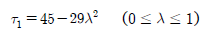
(1) For 4 cycle in-line diesel engines and 4 cycle vee type diesel engines with firing intervals of 45° or 60°, the value of 1 is given by the following formula:
(2) For 2 cycle diesel engines and 4 cycle vee type diesel engines other than shown in (1) above,
the value of 1 is given by the following formula:
 where:
1 = Allowable limit of torsional vibration stresses for continuous operation (N/mm2)
= Ratio of the number of revolutions to the number of maximum continuous revolutions.
2. Within the range below and at 80 % of the maximum continuous revolutions, the torsional vibration
stresses not exceeding 2 given in the following formula may be accepted, only for transient operation by passing through rapidly the range where the stresses exceed 1:

where:
2 = Allowable limit of torsional vibration stresses for transient operation (N/mm2)
3. The torsional vibration stresses are not to exceed 3 given in the following, within the range from the maximum continuous revolutions to 115 %.
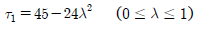
(1) For 4 cycle in-line diesel engines and 4 cycle vee type diesel engines with firing intervals of 45° or 60°, the value of 3 is given by the following formula:
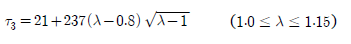
(2) For 2 cycle diesel engines and 4 cycle vee type diesel engines other than shown in (1) above, the value of 3 is given by the following formula:

where:
3 = Allowable limit of torsional vibration stresses in the range over the maximum continuous revolutions (N/mm2)
= As specified in Par 1.
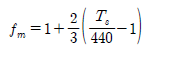
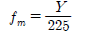
4. In case where the specified minimum tensile strength of the shaft material exceeds 440 N/mm2, or its yield strength exceeds 225 N/mm2, the values of 1, 2 and 3 given in Pars 1 to 3 may be increased by multiplying the factor fm given in the following formula:
(1) For 1 and 3
(2) For 2
where:
fm = Correction factor for allowable limit of torsional vibration stresses concerning the shaft material
Ts = Specified minimum tensile strength of shaft material (N/mm2). However, in case where the specified minimum tensile strength exceeds 590 N/mm2 for carbon steel forgings, or 835 N/mm2 for low alloy steel forgings, the value of Ts for calculating fm is to be as deemed appropriate by the Society.
Y = Specified minimum yield stress of the shaft material (N/mm2).
202. Intermediate shafts, thrust shafts, propeller shafts and stern tube shafts
1. For ships equipped with main propulsion diesel engine, the torsional vibration stresses on the intermediate shafts, thrust shafts, propeller shafts and stern tube shafts are to be in accordance with the following requirements (1) and (2). 【See Guidance】
(1) For continuous operation, the torsional vibration stresses are not to exceed 1 given in the following formulae:
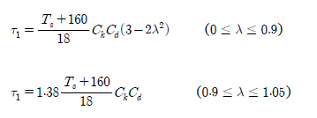
where:
1 = Allowable limit of torsional vibration stresses for continuous operation N/mm2.
= As specified in 201. 1.
Ts = Specified minimum tensile strength of shaft material (N/mm2). However, the values of Ts for using in the formulae is not to exceed 600 N/mm2 for carbon steel forgings and 800 N/mm2 for low alloy steel forgings in intermediate shafts and thrust shafts, and 600 N/mm2 in propeller shafts and stern tube shafts. Where propeller shafts and stern tube shafts are made of the approved corrosion resistant materials or other materials having effective means against corrosion by seawater, the value of Ts for using in the formulae is to be as deemed appropriate by the Society.
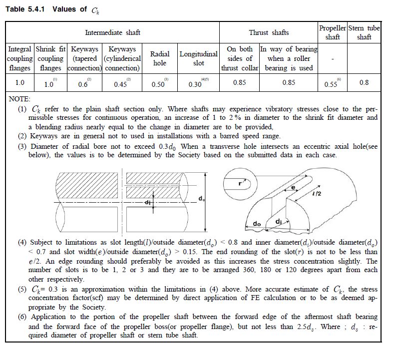
Ck = Coefficient concerning to the type and shape of the shaft, given in Table 5.4.1.
Cd = Coefficient concerning to the shaft size and determined by the following formula:
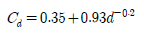
d = Diameter of the shaft (mm)
(2) Within the range below 80 % of the maximum continuous revolutions, the torsional vibration stresses not exceeding 2 given in the following formula may be accepted, only for transient operation by passing through rapidly the range where the stresses exceed 1.
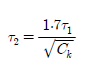
where:
2 = Allowable limit of torsional vibration stresses for transient operation (N/mm2)
1, Ck = As specified in (1)
2. For main propulsion system formed by steam turbines, gas turbines, diesel engines having slide couplings such as electro-magnetic coupling or fluid couplings, or electric propulsion systems, allowable limits of the torsional vibration stress on the intermediate shafts, thrust shafts, propeller shaft and stern tube shafts are to be as deemed appropriate by the Society. 【See Guidance】
203. Shafting system of generators
1. Torsional vibration stresses on the crankshafts of diesel engines to drive generators are to be in accordance with the following requirements (1) and (2). However, where the strength calculation for crankshafts is carried out according to the special requirements given by the Society, these stresses are to comply with the special requirements. 【See Guidance】
(1) The torsional vibration stresses are not to exceed 1 given in the following, within the range from 90 % to 110 % of the maximum continuous revolutions.
(A) For 4 cycle in-line diesel engines and 4 cycle vee type diesel engines with firing intervals of 45° or 60°, the value of 1 is given by the following formula:
1=21 N/mm2
(B) For 2 cycle diesel engines and 4 cycle vee type diesel engines other than shown in (A), the value of 1 is given by the following formula:
1=16 N/mm2
(2) Within the range below and at 90 % of the maximum continuous revolutions, the torsional vibration stresses not exceeding 2 given in the following formula may be accepted, only for transient operation by passing through rapidly the range where the stresses exceed 1.
1=31 N/mm2
2. The torsional vibration stresses on the generator shafts driven by diesel engines are to be in accordance with the following requirements (1) and (2).
(1) The torsional vibration stresses are not to exceed 1 given in the following, within the range from 90 % to 110 % of the maximum continuous revolutions.
1=31 N/mm2
(2) Within the range below and at 90 % of the maximum continuous revolutions, the torsional vibration stresses not exceeding 2 given in the following formula may be accepted, only for transient operation by passing through rapidly the range where the stresses exceed 1.
2=118 N/mm2
3. In case where the specified minimum tensile strength of the shaft material exceeds 440 N/mm2, or its yield strength exceeds 225 N/mm2, the values of 1 and 2 given in Pars 1 and 2 may be increased by multiplying the factor fm given in 201. 4.
204. Avoidance of major criticals
The major criticals of one node vibration in in-line diesel engine, e.g. the n th and n/2th order for 4 cycle and the nth order for 2 cycle (n denotes the number of cylinders), are not to exist within the following speed range except when an approval is specifically obtained by the Society:
For main propulsion shafting system 0.8 ≤ ≤ 1.1
For generator shafting system 0.9 ≤ ≤ 1.1
where
= Ratio of the number of revolutions at the major critical to the maximum continuous revolutions
206. Barred speed range
1. In case where the torsional vibration stresses exceed the allowable limit 1 specified in 201. to 203., the barred speed ranges are to be imposed in accordance with the following. The barred speed ranges are to be marked with red zones on the engine tachometers for passing through the ranges as rapidly as possible.
(1) the barred speed ranges are to be imposed between the following speed limits.
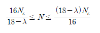
where:
N = The number of revolutions to be barred (rpm)
Nc = The number of revolutions at the resonant critical (rpm)
= Ratio of the number of revolutions at the resonant critical to the maximum continuous revolutions
(2) For controllable pitch propellers, both full and zero pitch conditions are to be considered.
(3) Restricted speed ranges in one cylinder misfiring conditions are to enable safe navigation even where the ship is provided with one propulsion engine.
2. In case where there are problems such as chattering or generation of heat caused by excessive alternating torque arising from the torsional vibration in the gears and flexible couplings, the requirement for those speed ranges is to comply with preceding Par 1. However, excessive alternating torque is not to be occurred in the speed range specified in 204.
GUIDANCE Part 5 Chapter 4
Section 2 Allowable Limit of Vibration Stresses
201. Crankshafts
1. In application to 201. of the Rules, the strength calculation for crankshafts is carried out according to the special requirements given by the Society means Annex 5-3. For the allowable limit of vibration stresses, the nominal alternating torsional stresses(N) specified in Annex 5-3, 2. (2) (A) are to be applied in the operational speed range of the engine. Where barred speed ranges are imposed, the allowable torsional vibration stresses in the ranges may be specially considered.
2. In application to 201. 4 of the Rules, in case where the specified minimum tensile strength of the crankshaft exceeds 590 N/mm2 for carbon steel forging, or 835 N/mm2 for low alloy steel forging, the value of Ts given in formula for fm is to be in accordance with the following.
(1)The value of Ts is to be taken as 590 N/mm2 for carbon steel forging, and 835 N/mm2 for low alloy steel forging. However (2) below is to be excepted.
(2)Where the crankshaft approved by Ch 2, Sec 5, 503. 2 of the “Guidance for Approval of Manufacturing Process and Type Approval, etc.” for torsional fatigue strength of crankshaft, the value of Ts is to be taken as the value added the fatigue strength improved.
202. Intermediate shafts, thrust shafts, propeller shafts and stern tube shafts
1. The allowable limit of torsional vibration stress for propeller shafts made of the approved corrosion resistance materials is to be calculated by the following formula in place of the formula for τ1 shown in 202. 1 of the Rules.
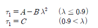
1 : Allowable limit of torsional vibration stress at the continuos operation (N/mm2)
: Ratio of the number of revolution to the number of maximum continuos revolution
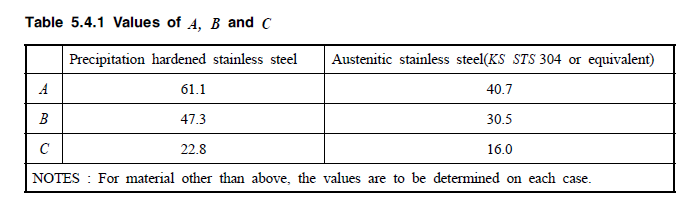
A, B, C : Constant dependent on shaft materials given in Table 5.4.1 of the Guidance
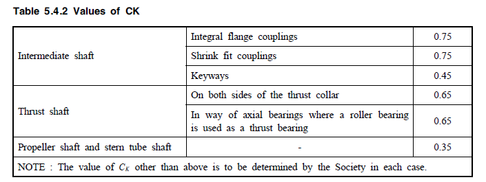
2. In the application 202. 2 of the Rules, the allowable limits of torsional vibration stress are to be calculated by applying the values of Ck given in the Table 5.4.2 of the Guidance in lieu of the formula specified in 202. 1 of the Rules.
3. In application to Table 5.4.1 NOTE (5) of the Rules, “as deemed appropriate by the Society” is to be in accordance with the following.
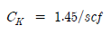
scf : stress concentration factor at the end of slots defined as the ratio between the maximum local principal stress and times the nominal torsional stress determined for the hollow shaft without slots.
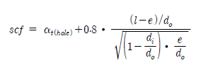
l : slot length (mm)
e : slot width (mm)
di : inside diameter of the hollow shaft at the slot (mm)
do : outside diameter of the hollow shaft (mm)
t(hole) : stress concentration factor of radial holes(in this context e = hole diameter) determined by the following formula

or simplied to t(hole) =2,3
However, this formula for above stress concentrate factor applies to the following slots.
(A) Slots at 120 or 180 or 360 degrees apart
(B) Slots with semicircular ends (A multi-radii slot end is not included in this empirical formula) (C) Slots with no edge rounding(except chamfering)
203. Shafting system of generators
1. In application to 203. of the Rules, the strength calculation for crankshafts is carried out according to the special requirements given by the Society means Annex 5-3. For the allowable limit of vibration stresses, the nominal alternating torsional stresses(N) specified in Annex 5-3, 2. (2) (A)
are to be applied in the operational speed range of the engine. Where barred speed ranges are imposed, the allowable torsional vibration stresses in the ranges may be specially considered.
205. Detailed evaluation for strength
Where the torsional vibration stress acted on shaft is satisfied with requirements of Ch 3, 204. 3 of the Guidance, D according to the requirements of Ch 3, 204. 3 of the Guidance may be taken instead of 1 given in Pt 5, Ch 4 of the Rules at the calculation for allowable limit of torsional vibration stress.