HOW TO ESTIMATE BEARINGS’ DISPLACEMENTS DUE TO HULL DEFLECTIONS
Dr.Yuriy Batrak, January 2020, Intellectual Maritime Technologies
It is far better to foresee even without certainty than not to foresee at all.
Henry Poincare
Whenever I tell naval architects about the nature of shaft alignment, and how accurately it should be performed, they are surprised, to say the least, because they know about the deflections values experienced by the double bottom in the engine room region. Especially when it comes to large vessels, such as tankers, bulk carriers, container ships, etc. I always explain that this is only about the initial offsets of bearings, and all modern software, such as our ShaftDesigner, take hull deflections into account in shaft alignment design in all specified operating conditions.
The fact of the significant impact of hull deflections on the displacement of shafting bearings has been known for at least 50 years, see, for example, [1, 2]. By the way, to anyone who is interested in shaft alignment knowledge I recommend to read book Memoirs of Marine Troubleshooter [3] by one of the authors of the article [2] G. C. Volcy.
A lot of researches has been done on the topic of hull deformations in the engine room region since then and a lot of articles and reports have been published. But, despite this, again and again, I see shaft alignment calculations, in which hull deflections are not mentioned at all, even when it comes to ship’s hulls made of light alloys. I see three possible reasons: either some shaft designers do not know at all that the hull deflections should be taken into account in the shaft alignment design, or they believe that the hull of the vessel is so stiff that the issue is not worth discussing, either (and this is most likely) they are not able to perform such calculations.
Indeed, what comes first to the mind of present-day engineers when it comes to calculating the deformations of hull structures in the engine room region? That’s right! This is a huge FEM model consisting of many thousands of elements. Recommendations on the use of such models can be found in the classification society’s rules. Shaft alignment designer, being sane people, understand that no one will ever give them a budget to create a FEM model of the hull structures for the purpose of calculating hull deflections. Unfortunately, few people think that an assessment of the hull deflections can be done without creating huge and expensive FEM models. For this, it is only necessary to apply basic knowledge from the hull structural mechanics, which every naval architect has in the pre-computer era. Such type of knowledge is embedded in the ShaftDesigner software algorithms for evaluating bearing displacements due to a hull deflections.
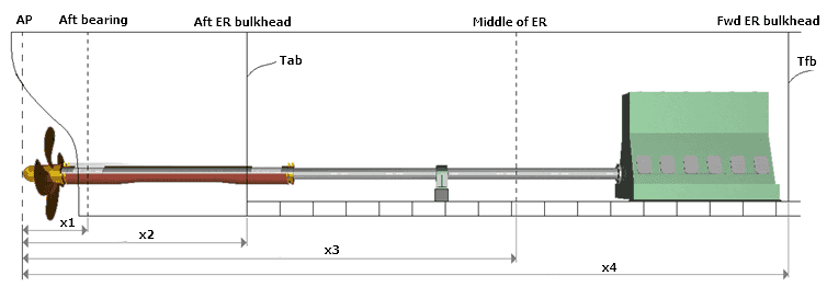
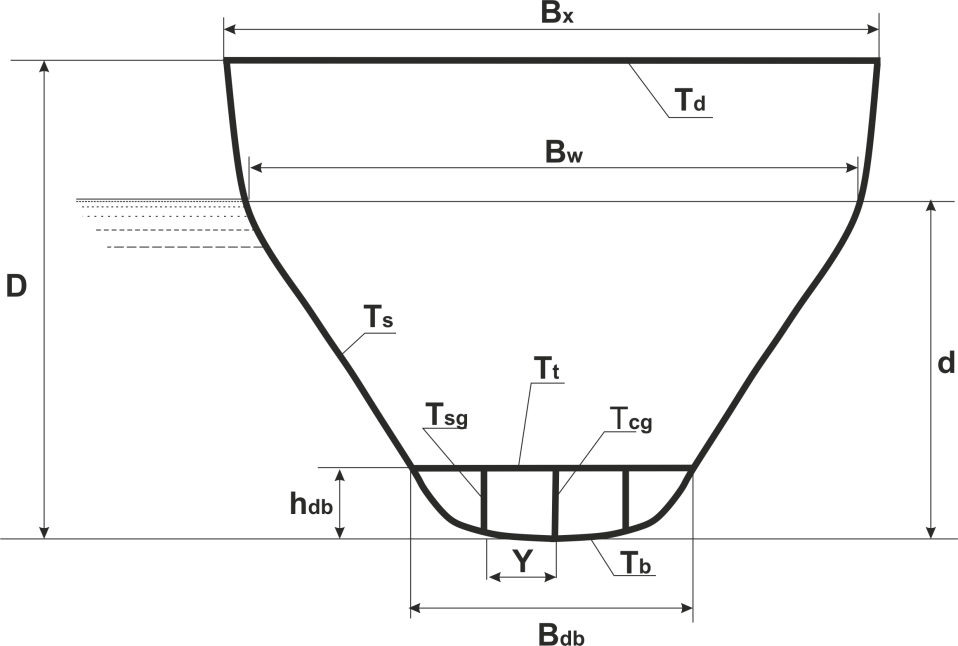
To calculate the displacement of the shafting bearings with ShaftDesigner software, it is necessary to draw up a simplified description of the hull structures in the engine room region. The compilation of such a description is available to every engineer who can read hull drawings. The essence of the initial data is clear from the sketches Fig. 1 and Fig.2 below.

Fig. 1 Longitudinal hull section

Fig. 2 Frame section at coordinate Xi
It should be said that there are a number of factors causing deformation of hull structures: hydrostatic pressure, weight load, temperature deformation due to the difference between the temperature of the deck structures and the temperature of the water, dynamic loads on the waves. Of particular note is the deformation of the hull in a dry or floating dock condition when the hull is supported by blocks. These deformations are not predictable and cannot be calculated due to the uncertainty of the load acting on the blocks. In this regard, performing of shaft alignment procedure in dock condition without buoyancy simulation (see our note “Shaft Alignment in a Dry Dock”) is fraught with unpleasant consequences.
One should pay attention to the fact that it is not enough to calculate only the ship hull girder bending, which is most often discussed when considering the issue of the effect of hull deformations. It is also necessary to calculate the local deflections of the bottom structures. Local deflections can give bearing displacements far superior to those caused by hull girder bending, Fig.3.

Fig. 3 Total hull deflections and bearing displacements
Since the shafting alignment procedure should be carried out afloat at the stage when all the heavyweights in the engine room region are onboard, most to the value of ship structures deformation contributes the hydrostatic pressure. The hydrostatic pressure changes with loading and unloading a ship, i.e. the main parameter for calculating bearing displacements due to hull deformations is a ship draft.
The contribution of other factors is also noticeable, but less significant. However, during the shaft alignment procedure, not only the draft of the vessel should be documented, but also the condition of the fuel and ballast tanks, the temperature of water and air, and the weather condition in relation to cloud cover. This information may be useful in the future when analyzing the causes of shafting failure if this happens, or during shafting realignment.
It should not be expected of course, that the used method allows calculating the displacements of the bearings due to hull deflections exactly but “It is far better to foresee even without certainty than not to foresee at all”.
References
- Nakashima S., Mano M. The deflections of engine room double bottom structures. – Shipping World and Shipbuilder, No 3866, Feb, 1972.
- Volcy G., Garnier H. Masson J. Deformability of the hull steelwork and deformations of the engine room of large tankers – International Shipbuilding Progress, vol. 21, August 1974, No 9.
- G. C. Volcy Memoirs of Marine Troubleshooter. The Institute of Marine Engineers, London, 1995.
