DNV-GL-2019.pdf (2087 downloads)
DNV GL
RULES FOR CLASSIFICATION SHIP July 2019
Part 4 Chapter 2 Section 4
ALIGNMENT
1 General
1.1 Application
1.1.1 This subsection is only applicable for propulsion plants. For geared plants, the calculations in this section are only applicable for the low speed shaft line, which shall include the output gear shaft with radial bearings. Vertical shaft alignment is always applicable, while horizontal alignment is applicable upon request.
The rule requirements applies to fully submerged propellers.
1.1.2 Calculation versus specification
Propulsion plants as described in [1.3.2] require shaft alignment calculation.
All other plants need a shaft alignment specification only, see [1.3.3].
1.1.3 Aft most bearing
Acceptance criteria and modelling of aft most bearing are dependent of risk:
— White metal lined aft stern tube bearing which is either double sloped, or has a journal diameter 500 mm or greater, shall fulfil bearing lubrication criteria defined in [2.1.6].
— Stern tube arrangements incorporating a single stern tube bearing only and where alignment calculation is required, shall fulfil bearing lubrication criteria defined in [2.1.6].
— Other propulsion plants where alignment calculation is required shall fulfil requirements in [2.1.5].
Guidance note:
Aft most bearing is in most cases to be understood as aft stern tube bearing, but can also be other designs e.g. strut mounted
bearings which are common in twin screw designs without skegs.
—e-n-d—o-f—g-u-i-d-a-n-c-e—n-o-t-e—
1.3 Documentation
1.3.2 Systems requiring shaft alignment calculation
Shaft alignment calculation report shall be submitted for approval for propulsion plants with one out of the following criteria:
— minimum shaft diameters (low speed side) of 400 mm or greater for single screw and 300 mm for twin screw
— gear transmissions with more than one pinion driving the output gear wheel, even if there is only one single input shaft as for dual split paths
— shaft generator or electrical motor as an integral part of the low speed shaft in diesel engine propulsion
— single stern tube bearing arrangement.
Upon request, shaft alignment calculations may also be required for unconventional hull forms, such as asymmetric aft ship, and/or novel propulsion arrangements, such as arrangements incorporating propulsion improvement devices (PIDs). Alignment calculations may also be required for other plants when these are considered sensitive to alignment.
Upon request, supporting analysis of propeller loads in normal and/or transient operation may be required, in cases where it is suspected that use of default propeller loads is not sufficient to ensure a robust aft stern tube bearing design.
For required content of a shaft alignment calculation report, see [2].
1.3.3 Systems only requiring shaft alignment specification
For all propulsion plants other than those listed in [1.3.2], a shaft alignment specification shall be submitted for information. The shaft alignment specification shall include the following items:
— bearing offsets from the defined reference line
— bearing slope relative to the defined reference line if different from zero
— installation procedure and verification data with tolerances e.g. gap and sag and jacking loads (including jack correction factors and jack positions) and verification conditions (cold or hot, propeller submersion, etc.).
2 Calculation
2.1 General
2.1.1 Calculation input data
The shaft alignment calculations shall at minimum include the following input data:
— propulsion plant particulars, e.g. rated power of main engine and propeller shaft rpm
— equipment list, i.e. manufacturer and type designation of prime mover, reduction gear (if applicable) and bearings
— geometry data of shafts, couplings and bearings, including reference to relevant drawings. For direct coupled plants, the crankshaft model shall be according to the engine designer’s guidelines
— propeller data
— bearing clearances.
2.1.2 Alignment conditions
The shaft alignment calculations shall include the following conditions:
— alignment condition (during erection of shafting)
— cold, static, afloat, fully submerged propeller
— hot, static, afloat, fully submerged propeller
— hot, running with hydrodynamic propeller loads.
For geared shafting systems:
— running conditions as required to verify gear acceptance criteria
— all relevant combinations of prime mover operation
— horizontal alignment is upon request.
2.1.3 Influence parameters
The shaft alignment calculations shall take into account the influence of:
— buoyancy of propeller
— thermal rise of machinery components (including rise caused by heated tanks in double bottom and other possible heat sources)
— gear loads (horizontal and vertical forces and bending moments)
— angular working position in gear bearings for gears sensitive to alignment, see guidance note 1
— bearing wear (for bearings with high wear acceptance e.g. bearings with water or grease lubrication)
— bearing stiffness (if substantiated by knowledge or evaluation, otherwise infinite)
— hull and structure deflections, see guidance note 2
— hydrodynamic propeller loads, see guidance note 3.
Guidance note 1:
For sensitive geared systems (e.g. gears with large face width or gears with more than one pinion driving the output wheel) even
small alignment offsets may have large influence on the gear face load distribution. In such systems, angular position of the shaft
has to be found by iteration. Vertical and horizontal offsets may be assessed by means of the vertical and horizontal forces in the
previous iteration step. Bearing clearances have to be taken into account, but the oil film thickness can usually be disregarded
(except for very light bearing loads). For fluid film bearings the angular working position may be estimated to 20 to 30° off the
direction of the force (except for very light bearing loads).
—e-n-d—o-f—g-u-i-d-a-n-c-e—n-o-t-e—
Guidance note 2:
Hull deflection is dependent of design, draught, trim, aft peak tank filling etc. Estimated deflections can be based on FEM
calculations, experience from similar designs etc. Larger safety margins should be applied when these deflections are unknown and
are expected to have influence on the alignment.
—e-n-d—o-f—g-u-i-d-a-n-c-e—n-o-t-e—
Guidance note 3:
[1.1.3] defines scope of aft most tail shaft bearing analysis dependent of risk. For propulsion plants where the aft mostbearing lubrication criteria are required, see [2.1.6]. For other plants, the hydrodynamic loads can be applied by either verified
measurements on similar designs or a default bending moment. The default bending moment should not be less than 0.05·T0
downward and 0.30·T0 upward, where T0 is propeller torque at MCR. For twin screw plants a range of ±0.3·T0 horizontally and
±0.2·T0 vertical should be used.
For unconventional hull forms or novel propulsion arrangements it may be necessary to extend the range of hydrodynamic loads
beyond the default values given herein.
—e-n-d—o-f—g-u-i-d-a-n-c-e—n-o-t-e—
2.1.4 Results
The shaft alignment calculations shall at minimum include the following results:
— bearing offsets from the defined reference line
— calculated bearing reaction loads and pressures
— bearing reaction influence numbers
— graphical and tabular presentation of the shaft deflections with respect to the defined reference line
— graphical and tabular presentation of the shaft bending stresses as a result of the alignment
— nominal relative slope between shaft and bearing centrelines in aft most propeller shaft bearing (see [2.1.5]) and if applicable, details of proposed slope-bore
— results from aft stern tube bearing lubrication criteria, see [2.1.6]
— in cases where a consideration of transient operation is required (upon request), resulting local bearing pressures shall be reported and evaluated by means of a detailed contact analysis (Finite element analysis)
— a shaft alignment procedure with verification method and data with tolerances (e.g. aft bearing slope and geometry, reference line, stern tube bearing offsets, calculated gap & sag values and jacking loads including jack correction factors). The procedure shall clearly state at which vessel condition the alignment verification shall be carried out (cold or hot, submersion of propeller etc.). Positions of jacks and temporary supports shall be specified. The procedure shall be possible to use again when in service.
2.1.5 Acceptance criteria
The shaft alignment shall fulfil the following acceptance criteria for all relevant operating conditions in [2.1.2]:
— acceptance criteria defined by manufacturer of the prime mover, e.g. limits for bearing loads, bending moment and shear force at flange
— acceptance criteria defined by the manufacturer of the reduction gear, e.g. limits for output shaft bearing loads and load distribution between bearings
— bearing load limits as defined by bearing manufacturer and Ch.4 Sec.1
— zero or very low bearing loads are only acceptable if these have no adverse influence on whirling vibration
— tolerances for gap and sag less than 5/100 mm are not accepted.
Acceptance criteria for aft most tail shaft bearing:
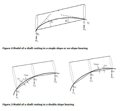
— in hot static and hot running conditions the relative nominal slope between shaft and aft most propeller shaft bearing should not exceed 3·10-4 rad (0.3 mm/m) and 50% of minimum diametrical bearing clearance divided by the bearing length, whichever is less. For definition of relative nominal slope, see Figure 1. This criterion is only applicable for single slope or no-slope bearings.
A white metal lined aft stern tube bearing which is either double sloped, or has a journal diameter 500 mm or greater, shall fulfil requirements regarding hydrodynamic lubrication performance as stated in [2.1.6].
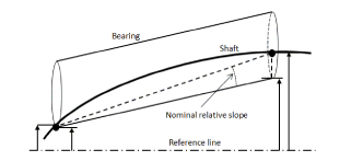
Figure 1 Relative nominal slope between bearing and shaft
2.1.6 Aft most bearing lubrication criteria
A white metal lined aft stern tube bearing which is either double sloped, or has a journal diameter 500 mm or greater, shall be designed to ensure hydrodynamic lubrication in all operational conditions. The minimum speed giving hydrodynamic lubrication (n0), shall be lower than the actual shaft speed (n). Both low speed and full speed criteria shall be fulfilled, see guidance note 1.
For multi slope bearings the method applies to the bearing segment with highest nominal bearing pressure for each operational condition.
For single stern tube bearing designs the aft bearing shall be of a multi slope design. However, for
installations with shaft diameter less than 400 mm (single screw) / 300 mm (twin screw), single sloped bearing design may be accepted provided compliance with the aft bearing lubrication criteria.
Low speed criterion:
The minimum shaft speed ensuring hydrodynamic lubrication (n0,stat) is calculated for:
— Hot static condition: no hydrodynamic propeller loads, n0,stat
nmin ≥ n0,stat
Full speed criterion:
The minimum shaft speed ensuring hydrodynamic lubrication (n0,dyn) is calculated for the following conditions defined by the vertical hydrodynamic bending moment acting on the propeller, see also guidance note 2 below:
— Hot running condition 1,n0,dyn1 :
— for single stern tube arrangements in general: 30% of full torque downwards
— for other conventional designs in general: 15% of full torque downwards.
— Hot running condition 2,n0,dyn2 :
— 30% of full torque upwards.
— For unconventional hull forms and/or novel propulsion arrangements, the range of propeller loads applied in the calculation may need to be extended beyond above values, based on special consideration.
nfull ≥ max(n0dyn1, n0dyn2)
The hydrodynamic propeller loads are defined as vertical bending moments as percentage of full speed
torque for conventional hull forms and propeller arrangements, see guidance note 2.
Formulations to be used for both low speed and high speed criteria:
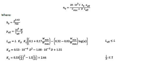
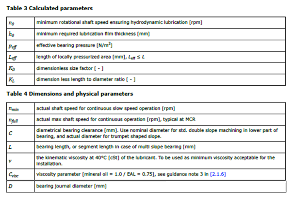
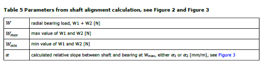
The parameters used in the above equations are defined in Table 3, Table 4 and Table 5.
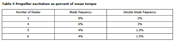
White metal lined stern tube bearings shall be modelled in the shaft alignment calculation as presented in Figure 3. This is achieved by modelling the bearing with a support point at either bearing end (or at either segment end for multi slope bearings). The total bearing stiffness shall not be taken less than 5·109 N/m, and stiffness of each individual support point not less than 2·109 N/m, unless documented otherwise.
The following results from the calculation shall be presented:
n0,stat , n0,dyn1 , n0,dyn2 , ν
Guidance note 1:
The calculation of minimum speed ensuring hydrodynamic lubrication is based on a quasi-empiric solution of the Reynolds equation
for journal bearings. Special conditions typical for stern tube bearings such as uneven load distribution and misalignment are
implemented. This method shall ensure lubrication in areas with maximum bearing pressure. The method shall set a limit for the
minimum continuous operational shaft speed and the minimum viscosity of the lubricant. Use of oil with high viscosity (above 200
cSt) generate viscous losses and heat, hence care has to be taken. The chosen viscosity (ν) is the minimum value to be used as
stern tube lube oil. The calculated oil film thickness (h0) is a parameter to be seen as an integrated element of the calculation
method, and shall not be understood as an acceptance of actual oil film thickness. (L/D) < 2 is a limitation in the calculation
method, and not a limitation of the actual bearing length.
The centre load in a double slope bearing (see W2 in Figure 3) can be distributed to both bearing segments as there will be an oil
film in both segments. The load shall then be distributed proportional to the end loads, from this it follows that W2aft is W2×W1/(W1
+ W3) and W2fwd is W2×W3/(W1 + W3).
The low speed criterion is calculated for hot static condition without any dynamic load, and limits the slow speed operation. Use of
turning gear is not seen as a continuous operation. It is not possible to fulfil the low speed criterion for very low speeds, but it is
recommended that steam plants operating with auto-spin shall have n0,stat not higher than 20 rpm. Electric propulsion plants able
to operate at low rpm should be special considered. Engine driven propulsion plants will have idle speed as nmin.
The full speed criterion includes the dynamic loads, and the criterion ensures that the oil film at full speed is able to handle a range
of different loads.
—e-n-d—o-f—g-u-i-d-a-n-c-e—n-o-t-e—
Guidance note 2:
The hydrodynamic propeller load range is chosen in order to safeguard the performance of the aft most propeller shaft bearing in
all running conditions. This includes both straight running at MCR and manoeuvring.
If the propeller tip in some operational conditions is above or in the vicinity of the water line, a downward bending moment may
occur even at slow speeds. Running with a semi-submerged propeller at high rpm may harm the bearing.
For twin screw propulsion plants, the alignment calculations should also include the propeller induced horizontal loads.
Manoeuvring at high vessel speed may generate large vertical and horizontal loads. The propeller induced loads are influenced
by the rotational direction of the propellers. Horizontal slope should be evaluated, but this requires a three dimensional analysis
which is not within scope of this rule paragraph. The angular working position of the shaft should not conflict with longitudinal oil
grooves.
—e-n-d—o-f—g-u-i-d-a-n-c-e—n-o-t-e—
Guidance note 3:
The viscosity parameter is based on findings in tests performed by DNV GL on biodegradable lubricants and mineral oils. The
test results show that there are differences between biodegradable lubricants and mineral oils that will affect the load carrying
capacity under certain conditions. The load carrying capacity is particularly important for some exceptional operational conditions
experienced during hard manoeuvring, mooring trials and operation with partly submerged propeller.
There should be a focus on optimizing the design rather than just increasing the viscosity. Generally, design optimization,
manufacturing/installation accuracy and careful running-in of the bearing are the key aspects to avoid potential failures.
It should be noted that when more research data become available, DNV GL will search for improved ways to handle the
differentiation between mineral oil and EAL, as found applicable. Thereby also ways to differentiate between EALs.
—e-n-d—o-f—g-u-i-d-a-n-c-e—n-o-t-e—
2.1.7 Verification data and tolerances
The tolerances in the alignment specification shall correlate with the tolerance ranges used in the
calculations. The final verification of the alignment shall be carried out afloat in at least one relevant
condition as mentioned in [2.1.2].
In special cases, verification in running condition by means of strain gauges and/or proximity transducers may also be required. In such cases the measurement program shall be submitted for approval.
Tolerances for misalignment in way of slope and straightness of stern tube bearings shall be defined. The tolerances shall reflect the calculation of lubricant film thickness see [2.1.6].
For single stern tube bearing designs the shaft alignment calculations shall consider the first inboard bearing load tolerance.
3 Installation
3.1 Inspection
3.1.1 Work to be completed before inspection
All large welding work in the vicinity of the shafting shall be completed before sighting process and insertion of propeller shaft. All large and heavy structure elements shall be in place before final verification of shaft alignment, see guidance note in [3.1.4].
3.1.2 Stern tube bearing validation
When shaft alignment calculations are required (see [1.3.2]), the stern tube bearing geometry shall be measured and reported in presence of the surveyor after mounting of bearings, but prior to insertion of the propeller shaft. Straightness, slope and ovality shall be within the specified tolerances. Each stern tube bearing shall be checked at minimum three longitudinal positions covering the whole length of the bearing.
Equal procedure shall be applied on each segment in case of multi slope bearing, see guidance note in
[3.1.4].For single stern tube bearing designs, laser aided or similar sighting method of stern tube bearings shall be used. A minimum of two bearings shall be included in the sighting process.
3.1.3 Shaft alignment tolerances
The shaft alignment shall be within the tolerances given in the shaft alignment specification, see guidance note in [3.1.4].
3.1.4 Alignment verification
When shaft alignment calculations are required (see [1.3.2]), the measured values of gap and sag and/or jacking loads with force-displacement diagrams and/or alternative verification data shall be reported in presence of the surveyor, see guidance note.
Guidance note:
Local effect verification: The designed geometry of stern tube bearings is based on the bearings ability to handle dynamic propeller
loads and weight loads from propeller shaft and propeller. The condition inside stern tube bearings is dependent of accuracy
both in design and installation. It has to be verified that the bearing’s slope(s), ovality and straightness are within the alignment
specification with defined tolerances before propeller shaft is inserted. Global hull deflections should have limited influence to the
alignment inside the stern tube, but welding in vicinity of the stern tube may disturb the alignment. Aftmost bearing mounted in
struts should be evaluated case-by-case.
Global effect verification: Mounting of large hull sections may introduce extra weight which should introduce global hull deflections.
Large welding works and launching may also introduce hull deflections. Final verification of global shaft alignment such as gap and
sag and/or jacking shall be carried out afloat with most of the hull completed.
—e-n-d—o-f—g-u-i-d-a-n-c-e—n-o-t-e—
For shafting installations not requiring approval, see [1.3.2], documentation of the installation of the shafting in accordance with the alignment specifications shall be presented to the surveyor.
3.1.5 Stern tube lubrication
Propeller shaft stern tube bearing lubricant type i.e. mineral oil/EAL, expected to be used in normal operation of the vessel shall be used during sea trials. Approved lubricant viscosity shall be confirmed during sea trials and documented. Suitable signboards shall be pasted at operating locations in machinery spaces and on the stern tube system tanks reflecting the minimum approved viscosity of the oil. The signboards shall differentiate between mineral oil and EAL.
Guidance note:
Approved oil viscosity is included in the shaft alignment calculations for aft bearing lubrication criteria.
—e-n-d—o-f—g-u-i-d-a-n-c-e—n-o-t-e—
Pt 4 Ch 4 Sec 1
2.9 Shaft bearings, dimensions
2.9.1 General
Radial fluid bearings shall be designed with bearing pressures and hydrodynamic lubrication thickness
suitable for the bearing materials and within manufacturers specified limitations.
For shaft bearings with significant pressure in plants operating at very low speeds (e.g. electric drives, steam plants or long term running on turning gear), hydrostatic bearings may be required.
The length of the aft most propeller shaft bearing shall be chosen to provide suitable damping of possible whirling vibration.
2.9.2 Oil lubricated bearings of white metal
For the aft most propeller shaft bearing, the nominal bearing pressure (projected area) shall be below 8 bar for all static conditions.
For other oil lubricated white metal bearings, higher pressures can be accepted within the limits specified by the manufacturer. Compliance with geometrical tolerances and precision of alignment assumed in manufacturer’s specification shall be verified in cases that the nominal pressure exceeds 12 bar in static condition.
The minimum length of the aft most propeller shaft bearing shall not be less than 1.5 times the actual journal diameter.Minimum permissible diametrical bearing clearance for the aft most propeller shaft bearing:
C ≥ 0.001 d + 0.2
C = diametrical bearing clearance [mm]
d = shaft outer diameter [mm]
2.9.3 Oil lubricated synthetic bearings
The permissible surface pressures shall be especially considered, but not to exceed those for white metal.
For the aft most propeller shaft bearing the nominal surface pressure (projected area) shall be below 6 bar for all static conditions.
The minimum length of the aft most propeller shaft bearing shall not be less than 1.5 times the actual journal diameter.
2.9.4 Water lubricated synthetic bearings
The permissible surface pressures shall be especially considered, but not to exceed those for white metal.
For the aft most propeller shaft bearing the nominal surface pressure (projected area) shall be below 6 bar for all static conditions.
The minimum length of the aft most propeller shaft bearing shall not be less than 2.0 times the actual journal diameter.
2.9.5 Separate thrust bearings
For separate thrust bearings the smallest hydrodynamic oil film thickness, taking into consideration the uneven load distribution between the pads, shall be larger than the sum of the average surface roughness of the thrust collar and pad (Ra_collar + Ra_pad).
2.9.6 Ball and roller bearings
Ball and roller bearings shall have a minimum L10a (ISO 281) life time that is suitable with regard to the specified overhaul intervals. The influence of the lubrication oil film may be taken into account for L10a, provided that the necessary conditions, in particular cleanliness, are fulfilled.
6.2 Shafting arrangement
6.2.1 The machinery and shafting shall be arranged so that neither external nor internal (self generated) forces can cause harmful effects to the performance of the machinery and shafting.
If shaft brake is fitted, it shall be arranged so that in case of failure in the actuating system, the brake shall not be engaged.
6.2.2 The shafting system shall be evaluated for the influence of:
— thermal expansion
— shaft alignment forces
— universal joint forces
— tooth coupling reaction forces
— elastic coupling reaction forces (with particular attention to unbalanced forces from segmented elements)
— hydrodynamic forces on propellers
— ice forces on propellers, see Pt.6 Ch.6 of the Rules for Classification of Ships
— hydrodynamic forces on rotating shafts:
i) outboard inclined propeller shafts or unshielded impeller shafts, see [6.3.1] 1)
ii) mean thrust eccentricity caused by inclined water flow to the propeller, see [6.3.1] 1) (Applicable to HS, LC and NSC)
— thrust eccentricity in water jet impellers when partially air filled or during cavitation, see [6.3.1] 2) — forces due to movements of resiliently mounted machinery (maximum possible movements to be considered)
— forces due to distortion or sink-in of flexible pads.
6.3 Shaft bending moments
6.3.1 The shaft bending moments due to forces from sources as listed in [6.2.2] are either determined by shaft alignment calculations, whirling vibration calculations, or by simple evaluations. However, two of the sources in [6.2.2] need further explanations:
1) The hydrodynamic force F on an outboard shaft rotating in a general inclined water flow may be determined as
F = 0.87 · 10-4 η v n d2 sinα (N/m shaft length)
d = shaft diameter (mm)
n = r/min of the shaft
v = speed of vessel (knots)
α = angle (degrees) between shaft and general water flow direction (to be taken as parallel to the bottom of the vessel)
η = “efficiency” of the circulation around the shaft. Unless substantiated by experience, it shall not be taken less than 0.6.
In order to determine the bending moments along the shaft line of an outboard shaft (as well as at the front of the hub), the bending moment due to propeller thrust eccentricity shall be determined e.g. as:
Mb=0.074 α D T/H (Nm)
D= propeller diameter (m)
T = torque (Nm), which may be taken as the rated torque if low torsional vibration level
H= propeller pitch (m) at 0.7 radius
The bending moment due to the (horizontal) eccentric thrust should be directed to add to the bending moment due to the hydrodynamic force F in the first bearing span.
2) The stochastic bending moment due to thrust eccentricity in a water jet impeller during air suction or cavitation is based on the worst possible scenario:
50% of the normal impeller thrust (FTH in N) applied at the lower half of the impeller, resulting in a bending moment as:
Mb=0.1 FTH D (Nm)
D= the impeller diameter (m).
TORSIONAL VIBRATION
Part 4 Chapter 2 Section 2
1.1 Application
1.1.1 Scope
The rules in this section apply to all shafting used in rotating machinery for propulsion, power production, steering and manoeuvring independent of type of driver except auxiliary plants with less than 200 kW rated power.
1.1.2 Simplification
Only mechanical active systems shall be included in the analysis. De-clutched branches shall not be required in the model. Electric power transmission, hydrodynamic couplings and torque converters shall not be seen as components transferring torsional vibrations; consequently systems in both ends can be handled as independent mass elastic systems.
1.1.3 Acceptance criteria
Acceptance criteria are found in the respective rule chapters for the components.
2 Calculation
2.1 General
2.1.1 Analysis conclusion
All analysis reports shall have a conclusion. In case of forced vibration analysis the conclusion shall be based on a comparison between calculated dynamic response and the permissible values for all the sensitive parts in the plant. Assumptions, conditions and restrictions shall be presented.
2.1.2 Input data quality
2.1.2.1 General
Parameters of importance which are uncertain, varying or nonlinear are handled by use of extreme values. It is not required to perform calculations with all combinations of these extreme data, but as a minimum the influence shall be quantitatively considered and also addressed in the conclusions.
2.1.2.2 Uncertain parameters
Variation of essential data such as dynamic characteristics of elastic couplings and dampers shall be
considered. Especially rubber couplings and certain types of vibration dampers may have wide tolerances of stiffness and damping.
2.1.2.3 Variation of parameter values
For components where the stiffeners is dependent on vibratory torque and/or temperature (as a consequence of power los), calculation where these dependencies are included may be requested.
2.1.2.4 Nonlinear characteristics
Systems with components having a strong nonlinear characteristic within the operation range with large influence on the system dynamics shall be simulated in time domain.
2.1.2.5 Source of data
The source of all essential data shall be listed in the vibration calculation report. For data that cannot be given as constant parameters, the assumed parameter dependency and tolerance range shall be specified.
2.2 Free vibration
2.2.1 Analysis content
Natural frequency calculations of the complete system are required. These shall include tables of relative displacement amplitudes, relative inertia torques, vector sums and, if used later, also their phase angles.
2.2.1.1 Specification of input data
Mass elastic system: Moments of inertia and inertia-less torsional elasticity/stiffness for each element in the complete system
2.2.1.2 Presentation of results
— Tables: relative displacement amplitudes, relative inertia torques, vector sums and, if used later, also their phase angles.
— Graphs: vibration mode shapes.
2.2.2 Calculation method
Calculation of relevant natural frequencies and their corresponding mode shapes shall be carried out by recognised calculation methods.
Guidance note:
Examples of recognised methods obtaining natural frequencies and their mode shapes are methodologies for direct matrix solutions calculating eigenvalues. Alternatively, approximate methods as the iterative Holzer’s method can be used. Damping has very little effect on natural frequency of the system, and hence the calculations for natural frequencies may be made on the basis of no damping.
—e-n-d—o-f—g-u-i-d-a-n-c-e—n-o-t-e—
2.3 Forced vibration frequency domain
2.3.1 Analysis content
Forced vibration shall include free vibration calculation see [2.2].
2.3.1.2 Specification of input data
Data to be specified as applicable:
— Engine: engine maker including type designation, rated power, rated speed, cycles per revolution, design (in-line/V-type), number of cylinders, firing order, cylinder diameter, stroke, stroke to connecting rod ratio, oscillating mass of one crank gear, excitation see [2.3.3].
— Vibration damper: type, damping coefficient, moments of inertia, dynamic stiffness.
— Elastic couplings: type, damping coefficient, moments of inertia, dynamic stiffness.
— Reduction/power take off (PTO) gears: type, moment of inertia for wheels and pinions, individual gear’s ratios per mesh, effective stiffness.
— Shafting: shaft diameter of crankshafts, intermediate shafts, gear shafts, thrust shafts and propeller shafts.
— Propeller: type, diameter, number of blades, pitch and expanded area ratio, moment of inertia in air, moment of inertia of entrained water (for zero and full pitch for CP propellers).
— Mass elastic system: values of all inertias, stiffnesses and damping values including propeller damping.
2.3.1.3 Presentation of output
The analysis report shall include:
— The results of the forced torsional vibration calculations shall be presented as relevant for the various components in the system.
— The results shall be presented as synthesis, including amplitude from the orders representing the largest contributions.
— The results shall be presented by graphs including acceptance values, see [2.5].
— Barred speed range, as applicable
— Where barred speed range is specified:
— maximum time for passing shall be specified, and within acceptance criteria [2.5.3]
— power margin value with associated engine and propeller curves.
Guidance note:
For propeller moment of inertia for entrained water, see requirements in Ch.5 Sec.1 [1.2.5].
—e-n-d—o-f—g-u-i-d-a-n-c-e—n-o-t-e—
2.3.2 Calculation method and model
2.3.2.1 Method and mass elastic system
The forced torsional vibration shall be calculated by means of linear differential equations, one for each lumped mass. Each mass shall be described by its inertia, connected by torsional springs to adjacent masses, damping described as absolute (mass) damping and relative (shaft) damping, and excitation applied on mass. Other recognized methods may be accepted upon request.
2.3.2.2 Representative parameter values
The parameters used in vibration calculations shall be representative for the actual speed, mean torque,
frequency, temperature, and vibratory torque. The latter implies that if an element is strongly dependent on the level of the vibratory torque and used in a linear vibration calculation, then the whole calculation may be made by iteration.
2.3.2.3 Two-stroke engine
Engine designer’s model and parameters shall be applied.
2.3.2.4 Propeller damping
In order to best represent the damping properties of a propeller, the Archer’s or Frahm’s approach with torque dependent damping coefficients should be used. Alternative methods using a dynamic magnifier or Schwanecke’s empirical approach or other approaches shall be subject to special consideration. For planing crafts damping shall be based on derivation of the actual torque characteristics, see guidance note.
Guidance note:
Propeller damping is a consequence of the propeller’s torque absorption characteristics, defined as C = dT/dω, where T is absorbed
torque and ω=(2πn/60). The torque characteristic for non-planning vessels can be formulated as T = nμ, where μ is 2 in steady
state condition, but is somewhat higher due to the superimposed vibratory torque.
The Archer number is defined as a= μ(60/2π). The corresponding Frahm number is Q ≈ a/9,545. Archer number is depending
on the actual propeller design and load, but is typically in the range 24-30 for conventional propellers. Dynamic magnifier for
absolute damping is defined as M = Jω/C, where J is propeller inertia and ω is actual vibration frequency. The corresponding
relative damping is ζ = (ω/ωn)/2M. Dynamic magnifier or relative damping should only be applied based on experience from
measurements of similar plants.
—e-n-d—o-f—g-u-i-d-a-n-c-e—n-o-t-e—
2.3.3 Excitation
2.3.3.1 Two-stroke engine
Engine excitation shall be based on harmonic tables of tangential crank pressure from engine designer
relevant for the actual engine with respect to type approval. Alternatively it can be based on measurements of cylinder pressure for the actual engine.
2.3.3.2 Four stroke engine
In addition to the methods for two-stroke engines, simplified methods with generic predefined pressure-time characteristics based on main engine data may be accepted.
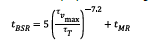
2.3.3.3 Propeller excitation
Propeller excitation can be taken as a percentage of the actual mean torque according to Table 5 unless other values are substantiated by the propeller manufacturer. The values are representative for max continuous forward operation. Propeller excitation for extreme steering manoeuvres of azimuth thrusters shall be taken as three (3) times the excitation in Table 5, unless other figures can be documented.
Systems where propeller phase is used actively in reducing response.
If propeller excitation is used for partial compensation of the engine’s excitation of same harmonic order (i.e. propeller phase optimization), this will require a specific computational fluid dynamics calculation (CFD) for the actual project, alternatively use 50% the table values.
2.3.3.4 Other excitations
Other excitation sources as electric drive control system, water jet impeller pulses, universal joints (second order), etc. may be considered when it influences the system behaviour.
2.3.4 Conditions
— normal operation. For engines, this shall be applied as uniform pressure distribution over all cylinders
— misfiring operation, only applicable for engines
— where the installation allows various operation modes, the torsional vibration characteristics shall be investigated for all possible modes, see guidance note.
Guidance note:
Examples of designs to investigate are installations fitted with controllable pitch propellers for zero and full pitch, power take
off gear integrated in the main gear or at the forward crankshaft end for loaded and idling generator, clutches for engaged and
disengaged branches.
—e-n-d—o-f—g-u-i-d-a-n-c-e—n-o-t-e—
2.3.4.1 Selection of misfiring cylinder
For calculation in misfiring condition the misfiring cylinder shall be selected as follows:
— for vibration modes and orders with vector sums almost equal zero, any cylinder may be selected
— for vibration modes with significant vector sums (e.g. > 0.1 relative to maximum cylinder amplitude)
either:
— the cylinder which has the opposite phase angle of the vector sum should be selected or
— calculating all combinations and presenting the worst.
2.4 Forced vibration time domain
2.4.1 Analysis content
2.4.1.1 Free vibration
Forced vibration shall include free vibration calculation, see [2.2].
2.4.1.2 Specification of input data
Engine data to be specified as applicable; brand, model, bore, stroke, piston rod length, number of cylinders, V-angle, firing sequence and max rpm.
2.4.2 Calculation method and model
2.4.2.1 Method and mass elastic system
The forced torsional vibration shall be calculated by numerical integration of differential equations as found relevant for the system modelled.
2.4.2.2 Simplified model
The mass elastic system for numeric simulation can be simplified in order to remove high natural frequencies. It is required to verify by natural frequency calculations that the simplified system has approximately the same lower (only the important) frequencies as the detailed system.
2.4.2.3 Presentation of results
Simulation results shall be presented by graphs. Resolution and choice of parameters shall reflect the
intention of the simulation.
2.4.3 Relevant cases for simulation
2.4.3.1 General
The result of transient vibration documentation shall contain the peak vibration level and an estimation of the equivalent number of cycles. The acceptance criterion is the peak torque (or stress) and the corresponding equivalent number of cycles that shall be used for the shaft calculations.
The equivalent number of cycles is defined as the number that results in the same accumulated partial
damage (Miner’s theory) as the real load spectrum. A detailed method for evaluating the equivalent number of cycles is presented in DNVGL-CG-0038.
Examples of scenario which may be relevant for transient vibration simulations are given in [2.4.3.2] to [2.4.3.6] below.
2.4.3.2 Ice impact loads
Dynamic response from ice impact loads shall be simulated in the time domain when:
— required by the ice class rules
— ice load may result in reduced shaft speed, which may be harmful or impose severe operational
limitations.
Guidance note:
Polar class rules require transient torsional vibration analysis Pt.6 Ch.6 Sec.6 [11.6.2], which in practice means time domain
simulation. Baltic ice class rules open up for both time domain and frequency domain analysis, but states that the intention is
estimation of extreme load Pt.6 Ch.6 Sec.2 [15.5.3.2]. Ice going vessels will also face an increased resistance which may be
similar to bollard pull condition. A drop in shaft speed into a barred speed range may limit operation, and also available power if
the engine has to go below the barred speed range.
—e-n-d—o-f—g-u-i-d-a-n-c-e—n-o-t-e—
2.4.3.3 Large inertia loads
For plants that have a major critical resonance below idling speed and a low ratio of engine inertia to driven machinery inertia, the transient vibration torque shall be considered. This applies e.g. to diesel generator sets with highly elastic couplings and similar propulsion plants without clutch.
2.4.3.4 Clutching-in
The calculation of the system shall determine:
— the peak torque in couplings and gears
— the first decreasing torque amplitudes
— the heat developed in the clutch
— the flash power in the clutch.
The clutch parameters such as the actuation pressure-time characteristics and if necessary also the changing coefficient of friction shall be used in the calculation.
The results shall not exceed the permissible peak torques and amplitudes in couplings and gears in addition to the permissible heat (J) and flash power (W) in the clutch.
Torque measurements during the clutching-in may be required. This applies when calculations indicate peak torques or amplitudes near the approved limits.
2.4.3.5 Short circuit in PTO driven generators
A possible short circuit in a generator shall not be detrimental for the power transmitting elements such as couplings and gears. The purpose of the calculation shall determine the peak torques and amplitudes that occur before the safety system (circuit breaker) is in action. The duration to be considered is one (1) second.
Guidance note:
If the excitation torque (in the air gap between rotor and stator) is not specified, it can be assumed as:
T = T0 [10 e-t/0.4 sin(Ω t) – 5 e-t/0.4 sin(2Ω t)]
where:
Ω/2π = the electric net frequency (50 or 60 Hz)
t = time in s.
—e-n-d—o-f—g-u-i-d-a-n-c-e—n-o-t-e—
2.4.3.6 Influence of speed governor
When the speed governor influence has been taken into account it shall be done in the time domain.
2.5 Acceptance criteria
If any result is close to the acceptance limit and there are uncertainties in the calculations, vibration
measurements may be required, see [4].
2.5.1 Availability of main functions
In specifying prohibited ranges of operation due consideration shall be given to ensure that the navigating and manoeuvering functions are not severely restricted.
2.5.2 Determination of barred speed range
Speed ranges or operating conditions where the following acceptance criteria are exceeded, shall be
barred for continuous operation. Corresponding signboards shall be fitted at all manoeuvring stands and all tachometers marked with red. The tachometers shall be accurate within the tolerance +/-0.01 n0. A barred speed range above λ=0.8 is not permitted.
The width of a barred speed range shall be determined as follows:
— range where permissible values are exceeded
— extend with tachometer tolerance in both ends
— further extension in case of unstable engine operation at any end of the barred range.
Guidance note:
For 2-stroke fixed pitch plants the width of the barred speed range should not be made unnecessary wide because this can result
in a too slow passage with the consequence of higher vibratory stress level and increased number of cycles with high stress level.
—e-n-d—o-f—g-u-i-d-a-n-c-e—n-o-t-e—
2.5.3 Time for passing barred speed range
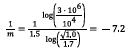
Barred speed range shall be passed rapidly and within the approved passing time tBSR. Unless otherwise is substantiated by a detailed fatigue evaluation of the propulsion shafting system, tBSR shall not exceed:
Where:
τVmax is peak torsional (steady state) stress [N/mm2] in the intermediate shaft within barred speed range
(calculated or measured, see also [3.1.2]).
τ T is maximum allowable transient stress [N/mm2], as calculated from relevant shafting rules (IACS UR M68 or τ max in DNVGL-CG-0038).
tMR is a passing time allowance [s] for intermediate shafts with design features ensuring a low stress
concentration factor, SCF ≤ 1.1. In such cases tMR may be taken as 10.0 [s]. For flanged shafts this requires a multi radii fillet design (see also Ch.4 Sec.1 [2.2.8.3] and for further explanation DNVGL-CG-0038). In this all other designs features.
The above is on the condition that the propeller shaft demonstrates the same or higher relative margin vs. the transient stress criterion as the intermediate shaft. Otherwise the ratio between τVmax and τT shall be adjusted accordingly, in the formula above.
Guidance note:
The formulation for tBSR is outlined from IACS UR M68, considering the slope of the S-N curve as derived from the allowable
transient stress level within BSR, assumed to correspond to 104 load cycles and the allowable continuous stress amplitude level
considered for 3·106 load cycles. As the formulations for allowable stresses in M68 implicitly include assumptions related to
correlation between speed ratio ( λ) and number of accumulated cycles during a “rapid” passing of BSR, an additional margin is
built into the formulation for tBSR, by means of increasing the slope of the initially constructed S-N curve with a factor of 1.5. This
facilitates a safe operation for installations with a longer passing time. For flanged intermediate shafts, the shaft feature design
factor (CK) in M68 equals 1.0, and the ratio between allowable transient and continuous stress amplitude becomes 1.7. The value
7.2 is in line with material properties for typical steel qualities and shall be applied independent of CK value.
Based on the M68 approach for shaft fatigue, the formulation for the exponent (slope of S-N curve) in the formula becomes:
For installations where the intermediate shaft peak stresses within BSR reach the maximum allowable transient stresses, DNV GL
defines 5 [s] as “rapid passing” and this is taken as basis for the TBSR formulation.
Compliance with the requirement in [2.5.3] is on this basis considered to be in line with corresponding requirements related to
rapid passing of BSR in IACS UR M51 and M68.
—e-n-d—o-f—g-u-i-d-a-n-c-e—n-o-t-e—
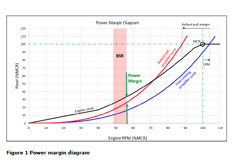
2.5.4 Power margin at BSR
Power margin at upper end of the barred speed range shall be sufficient to ensure a reasonable passing time of BSR in all expected operating conditions.
10% power margin is considered sufficient. However, if lower margin may be accepted, supported by
experience and/or extended analysis.
It is not required to verify the power margin at ship board testing.
Guidance note:
Main motivation for power margin is to have a requirement at design stage ensuring passing barred speed range within approved
time tBSR, see [2.5.3].
The predicted power margin (see Figure 1) is found comparing available engine power curve as provided by the engine maker to
the bollard pull curve for the designed propeller. The bollard pull curve is constructed according to the propeller law, with a bollard
pull margin vs. the free running propeller curve (including light running margin, LRM).
Bollard pull margin is to some extent design dependent. However, a default bollard pull margin of 17.5% is the basis for the power
margin requirement. Lower bollard pull margin may be applied when supported by more detailed propeller calculations and/or
experience data. In some cases, it is recommended to increase the bollard pull margin beyond the default value, in particular for
ships with relatively high service speed as these designs may have larger difference between bollard pull and free running propeller
characteristics.
—e-n-d—o-f—g-u-i-d-a-n-c-e—n-o-t-e—
2.5.5 Misfiring condition
Exceeding the acceptance limits in misfiring condition shall result in:
— restricted (e.g. < 0.5 hours) operation when the vibration level is acceptable for limited time (slow
heating of rubber elements)
— restricted driving or load condition (barred speed range or speed reduction, etc.)
— rejection when the vibration level may be critical as e.g. speed governor response, heating of rubber elements causing damping and stiffness to alter to further increase the vibration level, hard gear hammer, etc.
2.5.6 Shafts
Design requirements with acceptance criteria for shafts are found in Ch.4 Sec.1.
For plants with gear transmissions, the shafts (inside as well as outside the gearbox or thruster) shall be designed for at least the same vibration level as the gearing. Unless significantly higher vibrations are expected to occur somewhere in the shafting, documentation of the vibration levels in the shafts is not required.
For direct coupled plants the vibration level (τv) is not to exceed the values used for the shafting design with regard to continuous operation. Alternatively, the calculated vibration for continuous operation may be used for the shafting design.
For shafts that are designed on the basis of transient vibration, the torque amplitudes as well as number of equivalent cycles per passage are not to exceed the prerequisites for the shaft design.
Extended documentation to be submitted for designs where high cycle fatigue due to passing of barred speed range may be suspected, see guidance note. Extended documentation shall contain fatigue analysis supported by engine and propeller curves as relevant.
Guidance note:
In this context high cycle fatigue is expected when high transient stress amplitudes are combined with a large number of cycles.
Total number of cycles is dependent of cycles for each passing of barred speed range (BSR) and the vessel’s operation profile.
DNVGL-CG-0038 Calculation of shafts in marine applications may be used for fatigue analysis. DNVGL-CG-0038 calculates fatigue
capacity based on Wöhler curve (S-N curve) and Miner sum.
—e-n-d—o-f—g-u-i-d-a-n-c-e—n-o-t-e—
2.5.7 Crankshafts
Design requirements and acceptance criteria for crankshafts are found in Ch.3 Sec.1.
The permissible vibration torque (or shear stresses) and peak torque (only applicable to semi-built shafts) are determined in connection with the engine approval. Other criteria may also apply, such as acceleration at mass for cam drive branch or journal movements in bearings.
2.5.8 Vibration dampers
Design requirements and acceptance criteria for dampers are found in Ch.3 Sec.1.
Depending on the type of damper (viscous, rubber, steel spring) the following shall be considered:
— dissipated power (all kinds)
— vibration torque (rubber type and some steel spring types)
— vibration angle (some steel spring types).
The limits specified in the respective type approvals apply.
2.5.9 Torsional elastic couplings
Design requirements and acceptance criteria for torsional elastic couplings are found in Ch.4 Sec.5.
Torsional elastic couplings have design limitations with respect to:
— dissipated power
— vibration torque.
These limits are for continuous operation. Higher values may be accepted for a limited time of operation if twist amplitudes are monitored.
Transient vibration which occur occasionally (i.e. less than 50 000 times) such as clutching-in is not to exceed neither TKmax1 nor ΔTKmax.
Transient vibration which occur very infrequently indeed such as short circuit [2.4.3] are not to exceed
TKmax2.
Power loss need not be considered for transient operation.
2.5.10 Other couplings
Design requirements and acceptance criteria for actual components are found in Ch.4 Sec.4.
For other couplings and similar components such as membrane couplings, universal joints, link couplings, elements of composite materials, etc. the approved vibration torque shall not be exceeded.
Tooth couplings are limited with regard to cyclic torque reversals. The negative torque is not to exceed 20% of T0 unless especially approved.
2.5.11 Gear transmissions
Design requirements and acceptance criteria for gear transmissions are found in Ch.4 Sec.2.
The permissible vibration torque in gear transmissions is limited as:
1) In the full speed and load range (> 90% of rated speed and load) the vibration torque is not to exceed
(KA – 1)·T0 where KA is the application factor used in the gear transmission approval.
2) The vibration torque is limited to 35% of T0 throughout the entire operation range.
3) Gear hammer (negative torque) is not permitted except in unloaded power take off branches, where 20% of T0 (referred to the subject shaft speed) and 25% short duration misfiring is permitted.
4) Transient vibrations shall not cause negative torques of more than 25% of T0.
5) Transient peak torques shall not exceed the approved (KAP T0) or (1.5 T0).
2.5.12 Shrink fits including propeller fitting
Design requirements and acceptance criteria for shrink fits are found in Ch.4 Sec.1.
The estimated vibration torque shall not exceed the value used in the approval of the shrink fit connection.
Permissible vibration torque in shrink fit connections shall be considered for direct coupled plants and when
the peak torque in a barred speed range exceeds the peak torque at full load. Peak torque values during
misfiring operation shall be subject to special consideration.
2.5.13 Propellers
Design requirements and acceptance criteria for propellers are found in Ch.5 Sec.1.
No specific limitations apply unless specifically mentioned in connection with the propeller approval.
2.5.14 Thrusters
See Ch.5 Sec.3.
2.5.15 Electric rotating machines generators, pumps, compressors etc.
The vibration level shall not exceed any limitation specified by designer of the electric generator or motor.
2.5.16 Speed governor
The vibration levels at the sensor location of flexibly coupled propulsion engines shall not exceed the value specified by the engine manufacturer. If no value is specified and approved, tests and measurements shall be made in order to verify that the governor response is insignificant.
3 Shipboard testing
3.1 Check of barred speed range
3.1.1 Demonstration test
Where a barred speed range (BSR) is required, passages through this BSR, both accelerating and
decelerating, shall be demonstrated. This also includes when passing through the BSR in reverse rotational direction, especially during the stopping test. This applies both for manual and automatic passing-through systems.
3.1.2 Time recording
The BSR passing time shall be recorded. Passing time for accelerating ahead shall be equal to or below
the times specified in the approved documentation, see also [2.5.3]. Measurements shall be taken in trial condition.
Guidance note:
In cases where vibratory stresses are documented by strain gauge measurements and measured steady state stress values [4.2.5]
are less than calculated in approved documentation [4.2.5], the maximum allowable passing time may be adjusted accordingly,
according to the formulation in [2.5.3].
—e-n-d—o-f—g-u-i-d-a-n-c-e—n-o-t-e—
3.1.3 Border stability
The engine shall be checked for stable running (steady fuel index) at both upper and lower borders of the barred speed range. Steady fuel index means an oscillation range less than 5% of the effective stroke (idle to full index).
For controllable pitch propellers, this shall be tested with both zero and full pitch unless otherwise agreed.
Passing through a barred speed range shall be made in an optimum way. This means as quickly as possible.
If a specific procedure is given in the torsional vibration calculations, this shall be verified under the foreseen
operational conditions.
3.1.5 Misfire
Additional speed restrictions specified for misfire condition shall be verified, see [4.2.5]. Only applicable for conditions within engine limitations.
3.1.6 Signboard
When a barred speed range is required, signboards describing how to pass through shall be provided at all engine operating stands.
3.1.7 Alarm
For all installations where a barred speed range is introduced, an alarm shall be installed and initiated in the engine control room when passing time exceeds the approved value, see [2.5.3] and Ch.3 Sec.1 Table 10 [pos.10].
A reasonable delay time is accepted.
Guidance note:
A delay time of 5 seconds or 50% of approved passing time, whichever is the highest is considered reasonable. The intention with
the alarm is to alert the crew members about undesirable operating conditions for the propulsion shafting, and by that facilitate a
more favorable operation to the extent possible.
—e-n-d—o-f—g-u-i-d-a-n-c-e—n-o-t-e—
Guidance note:
Requirements to procedure and measurements are found in [4]. Compliance with IACS UR-M51.4 is achieved by fulfilling [3.1] and
[4].—e-n-d—o-f—g-u-i-d-a-n-c-e—n-o-t-e—
3.2 Check of gear hammer
Engines with elastic couplings shall be checked for stability of the speed governing system when provoked by misfiring. For selection of misfiring cylinder, see approved torsional vibration calculations.
Unless otherwise stated in the approved torsional vibration calculations, the following apply for each plant on board:
— Single engine plant: the entire speed range with either full pitch or combination pitch shall be checked. This may be done by a slow sweep or stepwise speed increase.
— Two-engine plants (with common reduction gear): the same applies, but the misfiring of the engines shall be combined. This may be done by keeping the selected misfiring for engine one, and first select a cylinder at random for the second engine and afterwards select the adjacent cylinder, see guidance note.
— Plants with more than two engines: special considerations apply.
— Diesel generator sets shall be checked at a minimum of 50% load and with another set operating in
parallel. All sets shall be tested.
— Speed ranges where gear hammer occurs due to one misfiring cylinder shall be restricted for continuous operation in that operation mode.
Guidance note:
Explanation to the two engine plant test: This is a test of low order (typical 0.5 order) instability and not two independent failures.
Hence, it is important that the two engines have different phase shift after a clutching in-out sequence, and that both engines
are misfiring in order to have enough imbalances to simulate worst case with 0.5 order resonance. Fuel rack oscillations peak to
peak (with combined misfiring for twin engines) less than 20% of the effective stroke (idle to full) are normally considered as
acceptable. For engines without fuel rack similar parameters are taken from engine monitoring system.
—e-n-d—o-f—g-u-i-d-a-n-c-e—n-o-t-e—
3.4 Check of transients during clutching-in procedure
After the clutch characteristics (pressure – time) are checked, the clutching-in shall be checked at the
minimum respectively the maximum permissible engine speed for clutching-in. The speed governing system shall respond with quickly damped oscillations.
3.5 Closed loop stability
The following may be requested, see type of speed governor:
— type and position of speed sensor.
Guidance note:
Evaluation of the torsional vibration system should be considered in case of conditions with high vibration at the governor pick up
position.
—e-n-d—o-f—g-u-i-d-a-n-c-e—n-o-t-e—
Pt 4 Ch.4 Sec.1
2.2.8 Simplified calculation method for shafts in direct coupled plants. IACS UR M68
1) This method may also be used for other intermediate and propeller shafts that are mainly subjected to torsion. Shafts subjected to considerable bending, such as in gearboxes, thrusters, etc. as well as shafts in prime movers are not included.
Further, additional strengthening for ships classed for navigation in ice is not covered by this method.
2) The method has following material limitations IACS M68.3:
Where shafts may experience vibratory stresses close to the permissible stresses for transient operation, the materials shall have a specified minimum ultimate tensile strength (σB) of 500 MPa. Otherwise materials having a specified minimum ultimate tensile strength (σB) of 400 MPa may be used.
Close to the permissible stresses for transient operation” means more than 70% of permissible value.
For use in the formulae in this method, σB is limited as follows:
— For C and C-Mn steels up to 600 MPa for use in item 4, and up to 760 MPa for use in item 3.
— For alloy steels up to 800 MPa.
— For propeller shafts up to 600 MPa (for all steel types).
Where materials with greater specified or actual tensile strengths than the limitations given above are
used, reduced shaft dimensions or higher permissible stresses are not acceptable when derived from the formulae in this method.
….
4) Permissible torsional vibration stresses:
The alternating torsional stress amplitude shall be understood as (τmax−τmin)/2 measured on a shaft in a relevant condition over a repetitive cycle.
Torsional vibration calculations shall include normal operation and operation with any one cylinder
misfiring (i.e. no injection but with compression) giving rise to the highest torsional vibration stresses in the shafting.
For continuous operation the permissible stresses due to alternating torsional vibration shall not exceed the values given by the following formulae:
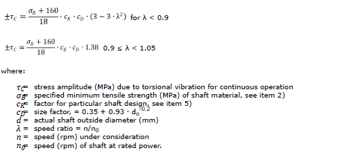
Where the stress amplitudes exceed the limiting value of τC for continuous operation, including one
cylinder misfiring conditions if intended to be continuously operated under such conditions, restricted
speed ranges shall be imposed, which shall be passed through rapidly.
In this context, “rapidly” means within just a few seconds, ≈ 4-5 seconds, both upwards and downwards.
Exceeding this time may require extended documentation of fatigue capacity. Detailed requirements for barred speed range are found in Ch.2 Sec.2 [2.5] and verification in Ch.2 Sec.2 [3.1].
Guidance note:
In order to increase fatigue capacity of flanged shafts (except propeller flange) stress concentration factor should be less
than 1.05. This may be obtained by means of a multi-radii design such as e.g. starting with r1 = 2.5 d tangentially to the
shaft over a sector of 5°, followed by r2 = 0.65 d over the next 20° and finally r3 = 0.09 d over the next 65° (d = actual
shaft outside diameter). A calculation method which is taking into account the accumulated number of load cycles and their
magnitude during passage of the barred speed range, may be used, see guidance note to [2.2.1].
—e-n-d—o-f—g-u-i-d-a-n-c-e—n-o-t-e—
Restricted speed ranges in normal operating conditions are not acceptable above λ = 0.8. Restrictedspeed ranges in one-cylinder misfiring conditions of single propulsion engine ships shall enable safe navigation.
The limits of the barred speed range shall be determined as follows:
— the barred speed range shall cover all speeds where τC is exceeded. For controllable pitch propellers
with the possibility of individual pitch and speed control, both full and zero pitch conditions have to be
considered
— the tachometer tolerance (usually 0.01·n0) has to be added in both ends
— at each end of the barred speed range the engine shall be stable in operation.
For the passing of the barred speed range the torsional vibrations for steady state condition shall not
exceed the value given by the formula:
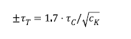
where:
τT = permissible stress amplitude in N/mm2 due to steady state torsional vibration in a barred
speed range.
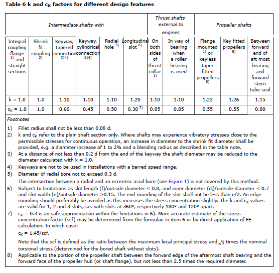
5) Table 6 shows k and cK factors for different design features. See IACS UR M68.6.
Transitions of diameters shall be designed with either a smooth taper or a blending radius.
Guidance note:
For guidance, a blending radius equal to the change in diameter is recommended.
—e-n-d—of—g-u-i-d-a-n-c-e—n-o-t-e—
6) Notes:
A. Shafts complying with this method IACS UR M68.7 satisfy the load conditions in [2.2.2].
a) Low cycle fatigue criterion (typically < 104), i.e. the primary cycles represented by zero to full load
and back to zero, including reversing torque if applicable. This is addressed by the formula in 3).
b) High cycle fatigue criterion (typically >>107), i.e. torsional vibration stresses permitted for
continuous operation as well as reverse bending stresses. For limits for torsional vibration stresses
see 4).
The influence of reverse bending stresses is addressed by the safety margins inherent in the formula
in 3).
c) The accumulated fatigue due to torsional vibration when passing through a barred speed range
or any other transient condition with associated stresses beyond those permitted for continuous
operation is addressed by the criterion for transient stresses, see 4).
B. Explanation of k and cK.
The factors k (for low cycle fatigue) and cK (for high cycle fatigue) take into account the influence of:
— the stress concentration factors (SCF) relative to the stress concentration for a flange with fillet radius
of 0.08 d0 (geometric stress concentration of approximately 1.45)
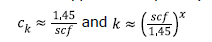
— where the exponent x considers low cycle notch sensitivity
— the notch sensitivity. The chosen values are mainly representative for soft steels (σB < 600), while the
influence of steep stress gradients in combination with high strength steels may be underestimated
— the size factor cD being a function of diameter only does not purely represent a statistical size
influence, but rather a combination of this statistical influence and the notch sensitivity.
The actual values for k and cK are rounded off.
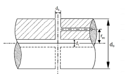
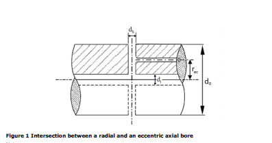
C. Stress concentration factor of slots
The stress concentration factor (SCF) at the end of slots can be determined by means of the following
empirical formulae using the symbols in footnote 6) in Table 6:
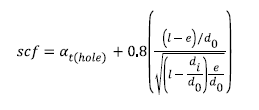
This formula applies to:
— slots at 120°, 180° or 360° apart
— slots with semi-circular ends. A multi-radii slot end can reduce the local stresses, but this is not
included in this empirical formula
— slots with no edge rounding (except chamfering), as any edge rounding increases the SCF slightly.
α t(hole) represents the stress concentration of radial holes (in this context e = hole diameter), and can
be determined from:
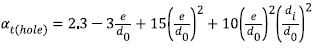
or simplified to: αt(hole) = 2.3.
Pt 6. Ch.2 Sec 10 Shaft Alignment – shaft align (July 2018)
1 Objectives
This section provides a set of requirements with the objective of enhancing the design, installation and
operating margin of the propulsion shaft bearings beyond the main class requirements for shaft alignment,see .
2 Scope
The objectives are met by the following scope additional to that of main class:
— increased range of applied hydrodynamic propeller loads
— mandatory use of oil film criterion in alignment calculations irrespective of shaft dimensions
— introduction of multi sloped aft bearing
— stricter requirements to bearing sighting
— additional monitoring requirements
— utilization of more advanced calculation methods (CFD & FEM) for Shaft align(2).
3 Application
The additional class notation Shaft align applies to main propulsion shafting installations using oil as the lubricant medium for white metal propeller shaft bearings, complying with the design, installation and testing requirements included in this section. For geared installations, the requirement applies to the low speed shaft line
5 References
— Pt.4 Ch.2 Sec.4 Shaft alignment
— Pt.4 Ch.4 Sec.1 Shafting
— DNVGL-CG-0283 Shaft alignment.
7 Design requirements
7.1 Shaft align(1)
Shaft alignment calculation shall be approved in accordance with Pt.4 Ch.2 Sec.4 irrespective of shaft
diameter.
7.1.1 Lubrication criteria
The design shall comply with aft bearing lubrication criteria defined in Pt.4 Ch.2 Sec.4 [2.1.6] irrespective of shaft diameter.
Hydrodynamically induced downward bending moment from the propeller shall be extended to 30% MCR Torque for aft bearing lubrication criterion in hot running condition .
Guidance note:
The above mentioned 30 % downward acting bending moment is considered as a criterion only for aft bearing lubrication. Impact
on adjacent bearings is not required to be considered for this condition i.e. unloading of the adjacent bearing is acceptable.
—e-n-d—o-f—g-u-i-d-a-n-c-e—n-o-t-e—
7.1.2 Aft most propeller shaft bearing design
Aft propeller shaft bearing shall be of a multi sloped design and manufactured using a white metal alloy material with Tin as the major constituent.
For installations with shaft diameter less than 400 mm (single screw)/300 mm (twin screw), single sloped bearing design may be accepted provided that compliance with the aft bearing lubrication criteria is documented for the same range of hydrodynamic propeller loads defined in [7.1.1].
7.1.3 Propeller immersion
Vessel’s design shall ensure complete propeller immersion under normal continuous operating conditions unless additional requirements according to [7.2.4] are complied with.
Means of warning against incomplete propeller immersion shall be provided in the wheel house and the central alarm panel. Suitable signboards shall be posted at operating locations.
Guidance note:
Alarm initiated by the aft draught gauge may be considered as a means of warning.
—e-n-d—o-f—g-u-i-d-a-n-c-e—n-o-t-e—
7.1.4 Single stern tube bearing installations extended criteria
For single stern tube bearing installations, the design, including the maximum bearing load specified in the jack load test tolerance for the first inboard bearing, shall comply with the aft bearing lubrication criteria.
Guidance note:
A raised intermediate bearing increases the relative slope in way of the aft bearing and consequently reduces the contact area.
—e-n-d—o-f—g-u-i-d-a-n-c-e—n-o-t-e—
7.1.5 Inboard shaft bearings on top of heated tanks
Where inboard shaft bearings are installed on top of heated tanks, the tank space shall be provided with a high temperature alarm. The alarm shall be set at the maximum temperature allowed for thermal expansion in the shaft alignment calculations.
Guidance note:
Alarm may be omitted with if shaft alignment calculations allow for thermal expansion with a minimum value of 100 °C in the tank
spaces.
—e-n-d—o-f—g-u-i-d-a-n-c-e—n-o-t-e—
7.1.6 Lubrication system
The stern tube shall be provided with a forced lubrication system fitted with a heat exchanger.
The lubrication system shall be designed to ensure satisfactory circulation of oil through the aft stern tube bearing by introduction of oil in the space between the aft sealing arrangement and the aft end of the bearing.
Forced lubrication may be omitted in case of retrofits, unless deemed necessary based on damage history.
7.1.7 Stern tube aft bearing temperature monitoring and alarm
Aft most bearing temperature shall be monitored and alarms shall be provided in accordance with Table 4.
7.1.8 Stern tube oil condition monitoring
Lubrication system shall be designed to make it possible to take representative oil samples under running conditions.
7.2 Shaft align(2)
7.2.1 In addition to the requirements for Shaft align(1) class notation, the following requirements shall be met:
7.2.2 Influence of propeller induced forces and bending moments
Shaft alignment calculations shall take into account hydrodynamically induced propeller forces and moments based on CFD aided calculations for the following conditions:
— Straight ahead running at MCR at design draught.
— Transient turning conditions, as a minimum including “hard over” turn with rudder angles of 35 deg. To both port and starboard. Turn shall be initiated from MCR straight ahead condition at design draught.
— In case normal operating conditions include partially immersed propeller, the condition expected to
result in “worst case” propeller loads in terms of local bearing pressures shall be incorporated (e.g. least
allowable propeller submersion combined with maximum allowed propeller RPM).
— Other critical conditions as found relevant, when motivated by experience of the designer, ship yard or the Society such as ballast condition, crash stop manoeuvers, etc.
The CFD model shall include the actual geometry of hull and propeller as well as relevant appendixes,
such as struts, ducts or PID’s.
Guidance note:
Guidelines for how to carry out CFD calculations are given in DNV GL class guidelines DNVGL-CG-0283
—e-n-d—o-f—g-u-i-d-a-n-c-e—n-o-t-e—
7.2.3 Lubrication criteria
For the straight ahead running condition, the aftmost bearing lubrication criterion for “hot running condition 2” defined in Pt.4 Ch.2 Sec.4 [2.1.6] shall be complied with, applying resulting propeller loads as derived from the CFD calculations. However, an additional margin of 10% MCR torque shall be added to the predicted
upward bending moment. These loads supersede the default values applicable for main class and Shaft align(1).
For the “hot running condition 1” compliance with the aftmost bearing lubrication criterion shall be
documented applying a propeller load similar to as for Shaft align(1) i.e. corresponding to a downward bending moment of at least 30% MCR torque.
The lubrication criterion shall also consider operation with a partly immersed propeller when relevant.
7.2.4 Evaluation of aftmost bearing pressures
Contact area and pressure distribution in the aftmost bearing shall be calculated by means of finite element analysis. As a minimum, results for the following conditions shall be presented:
— Conditions defined in [7.2.2] above.
— Hot static condition (no hydrodynamic propeller loads).
Guidance note:
FE analysis need not include effect of an oil film. Respective criteria for pressure/contact area are defined in DNVGL-CG-0283.
—e-n-d—o-f—g-u-i-d-a-n-c-e—n-o-t-e—
7.2.5 Hull deflections
Upon request, hull deflections including all relevant loading conditions shall be considered in the shaft
alignment calculations.
Guidance note:
Predictions of hull deflections should be submitted upon request bythe Society. This may typically be applicable for vessels with
long shaft lines or on installations where hull deflections are expected to have a significant influence on the shaft line offsets or the
aft propeller shaft bearing lubrication criteria.
—e-n-d—o-f—g-u-i-d-a-n-c-e—n-o-t-e—
9 Installation inspection
9.2.1 Stern tube bearing housing
Records of measurements of the housing inner diameter in way of the bearings shall be submitted for review by the surveyor.
Laser aided sighting of vertical and horizontal offsets of the stern tube housing in way of the bearings shall be submitted for review by the attending surveyor. A minimum of 5 reference points shall be used covering the aft most bearing housing and 3 reference points for the forward bearing housing. The laser reference line shall be made concentric with the stern tube and independent of the bearings.
For pre-fabricated stern tubes delivered to the Yard with bearings assembled, records of the same from the manufacturer shall be submitted to the surveyor.
Alternative means of measurement with equivalent accuracy may be considered upon special consideration by the Society.
Guidance note:
Spigots (recess) of aft and forward seal flanges are normally concentric with the stern tube bore unless machined at an offset for
adjustment of seal tolerances
—e-n-d—o-f—g-u-i-d-a-n-c-e—n-o-t-e—
9.2.2 Aft bearing push fitting procedure
Aft bearing push fitting procedure shall be carried out in accordance with a pre-defined procedure and
verified within calculated design limits.
9.2.3 Sighting of stern tube bearings after installation
Laser aided sighting of the stern tube bearings including offsets and slopes shall be carried out.
A minimum of two bearings shall be included in the laser aided sighting process, alternatively this may be a combination of the aft bearing and the first inboard support.
For the aft bearing, a minimum of 5 measurement points shall be included covering the effective length of the bearing including one at the knuckle point(s) for multiple slopes. There shall be a minimum of 3 measurement points in each of the slope segments. The laser reference line shall be the same as in [9.2.1] above.
For the forward stern tube bearing, a minimum of 2 measurement points apply.
In addition, measurements of the inner diameter of the bearings shall be submitted for review by the
surveyor.
9.2.4 Gap/sag process
Gap and sag process shall be done afloat using a dial gauge or laser or any method of equivalent accuracy. Feeler gauges are not permitted.
9.2.5 Jack loads
Cold static jack loads shall be carried out in floating condition for:
— inboard shaft line bearings including forward stern tube bearing, if installed
— 3 aft most engine bearings for directly coupled two stroke engines
— the aft main gear bearing for geared propulsion plants.
Hot static jack loads may be required for alignment sensitive designs.
— If any hull deflections are incorporated in shaft alignment calculations, representative jack load tests shall be carried out as defined in the approved alignment procedure. The applicable loading conditions shall be specified for consideration and acceptance by the Society.
Guidance note:
Load cells or equivalent devices are recommended to eliminate internal friction of the jacking device used for jack load tests.
—e-n-d—o-f—g-u-i-d-a-n-c-e—n-o-t-e—
LATERAL AND AXIAL VIBRATION
Pt 4 Ch 2 Sec 3
1 General
1.1 Application
1.1.1 Scope
The rules in this section apply to all shafting used in rotating machinery for propulsion, power production, steering and manoeuvring independent of type of driver except auxiliary plants with less than 200 kW rated power.
1.1.2 Vibration regimes
The following vibration regimes are covered within this section:
— lateral vibrations are handled as whirling, see [2]
— axial vibration see [3].
The following regimes are covered in other rule chapters:
— torsional vibrations, see Sec.2
— engine flexible mounting, see Ch.3 Sec.1
— vibration level as environmental requirement, see Ch.1 Sec.3
— class notations related to vibrations, see Pt.6 Ch.8 Sec.1 and Pt.6 Ch.8 Sec.2.
1.1.3 Acceptance criteria
Acceptance criteria for components are found in the respective rule chapters for the components.
1.1.4 Coupled vibrations
Axial vibrations initiated by torsional vibrations can be handled as independent, but with the radial component of excitation from the cylinder forces.
1.1.5 Forced vibration analysis
Time domain simulation may be requested in addition to forced vibration calculation in the frequency domain for transient analysis.
1.3 Documentation requirements
1.3.1 Documentation shall be submitted as required by Table 2….
Guidance note 1:
Lateral vibration calculation may be requested during approval of shaft arrangement. Examples of sensitive designs are shafts with
large bearing span/shaft diameter ratio, propellers with large overhang from aft most bearing, flexible support of aft most bearing
as typical for twin screw designs, large inertias without bearing support, tooth couplings without bending stiffness.
—e-n-d—o-f—g-u-i-d-a-n-c-e—n-o-t-e—
Guidance note 2:
Axial vibration calculation may be requested during approval of shaft arrangement. Examples of sensitive designs are long stroke
two-stroke engines without axial damper, shafting with length above 40 m, flexible couplings with interaction between torque and
axial deflection, propeller designs where natural blade bending frequency is equal to natural axial shaft frequency.
—e-n-d—o-f—g-u-i-d-a-n-c-e—n-o-t-e—
1.3.4 Drawings of the complete shafting arrangement shall be included in the design analysis. Typedesignation of prime mover, gear, elastic couplings, driven unit, shaft seals etc. shall be stated on the drawings. The drawings shall show all main dimensions as diameters and bearing spans, bearing supports and any supported elements as e.g. oil distribution boxes.
1.3.5 The vibration calculations shall be accompanied by an analysis, which shall compare the result of the calculation with the acceptance levels for all components in the system as relevant, and conclude with respect to possible restrictions. Assumptions, conditions and restrictions shall be presented.
2 Lateral vibration
2.1 Analysis
2.1.1 Extent and method of calculation
As a minimum, the calculations shall include the natural frequencies and mode shapes of the relevant
vibration modes.
2.1.2 Uncertain and variable parameters
A variation of parameters shall be included in the analysis in case of uncertain or variable important
parameters.
Guidance note:
Important but uncertain parameters as stiffness of aft stern tube bearing, resulting bearing load position, bearing load distribution
over length (if calculating with distributed bearing reaction), entrained water on propeller, etc. shall be varied within their probable
range and natural frequencies to be presented as corresponding graphs.
—e-n-d—o-f—g-u-i-d-a-n-c-e—n-o-t-e—
2.1.3 Entrained water to propeller
Calculation of entrained water shall be presented.
2.1.4 First order acceptance criteria
Resonance with the shaft speed (1st order forward whirl) shall have a separation margin of at least 20% to the operating speed range, guidance note.
Guidance note:
Example: a system with idle at 20 rpm and MCR at 100 rpm shall not have a 1st order fwd whirl in the range 16 rpm to 120 rpm.
—e-n-d—o-f—g-u-i-d-a-n-c-e—n-o-t-e—
2.1.5 Higher order acceptance criteria
Resonance caused by propeller blade passing (blade order) shall be avoided in the upper operating speed range unless it is substantiated that resonance will not cause harmful response, see guidance note.
Guidance note:
Approval is based on an over-all evaluation, and resonance should be avoided in the range 80 – 120% of MCR speed. Exceptions
may be given: along shafting with many bearings is not found sensitive if the propeller is the main excitation source and the mode
shape indicates resonance in forward end of shafting. Also bearing designs where good damping is expected, e.g. high bearing
length to diameter ratio combined with a bouncing vibration mode, may justify acceptable resonance response at high rpm.
—e-n-d—o-f—g-u-i-d-a-n-c-e—n-o-t-e—
2.1.6 Presentation of results
Results shall be presented both in way of numerical values and graphical e.g. as a Campell diagram. Mode shapes of the natural frequencies shall be presented.
3 Axial vibration
3.1 Analysis
3.1.1 Extent and method of calculation
As a minimum, the calculations shall include the natural frequencies and mode shapes of the relevant
vibration modes.
3.1.2 Uncertain and variable parameters
If the lowest vibration mode (with the node in the thrust bearing) is of significance to the conclusion, the calculations shall be made with various thrust bearing stiffness in order to see the influence of an estimation error.
3.1.3 Acceptance criteria free vibration
If major critical resonance occurs near or in the operational speed range and no damper is foreseen, forced axial vibration calculations shall be required.
3.1.4 Acceptance criteria forced vibration
In crankshafts, the stresses due to axial vibration shall not exceed the values used in connection with the engine approval. The amplitudes at the front end of the crankshaft shall be within the engine designer’s specified limit.
3.1.5 Presentation of results
Results shall be presented both in way of numerical values and graphical of the mode shapes of the natural frequencies.
4 Measurements
4.1 Axial vibration
Measurements of axial vibrations shall be required if major critical resonance occurs near or in the operational speed range and no damper is foreseen.