Dr.Yuriy Batrak, June 2019
TOLERANCE ASPECT OF RATIONAL SHAFT ALIGNMENT DESIGN
Failures of the propulsion installations occur with enviable constancy. According to The Swedish Club information among 1221 machinery claims, occurred between 2012 and 2017, 277 claims (22,7%) are associated with propulsion, not including main engine failures. The experts believe that the reason of a significant part of shafting claims is not appropriate shaft alignment, because failures are being seen during mooring trials, sea trials and within the first few weeks or month in service (MP August/September 2018).
Awareness of the proper propulsion shafting line alignment importance arose long ago. The concept of “rational alignment” is known for about 60 years. Since then a lot of shaft alignment techniques were developed and special design procedure, known now as a ‘shaft alignment calculation’, became widely used. From our point of view, the name of this procedure is somewhat incorrect because there is an infinite set of acceptable solutions for rational alignment and engineers face the problem of choosing one of them. That’s why it is more correct to call the procedure of finding the appropriate shaft alignment as a ‘shaft alignment design’ because the procedure of decision making for choosing of the rational solution from plenty available is typical for any design activity.
The goal of shaft alignment design is a spatial arrangement of bearings, expressed as bearings’ initial offsets relative to a given reference line. It would seem the rational solution, as it is currently understood by most of the shaft designers, should ensure a safe propulsion shafting alignment, but what is the reason failures of propulsion shafting continue to happen?
If exclude from consideration the improper implementation of shaft alignment procedure at the shipyard, materials failures, failures connected with torsional and axial vibration the reason should be sought exclusively in the shaft alignment design.
There are three possible causes connected with shaft alignment design leading to shafting failures:
- some of the specific operational states with their loads are not taken into account;
- the tolerances to compensate for various deviations from the design parameters are not provided;
- conditions for excessive whirling vibration due to unfavorable shaft alignment design have arisen.
Rational shaft alignment design should provide proper distribution of bearings’ loads in all normal ship conditions, stable lubrication of bearings, acceptable shaft bending stresses and crankshaft deflections in both static and running conditions for the fully laden ship and for the ship in ballast. Propeller hydrodynamic loads, hull deflections, bearings thermal growth are also to be taken into account.
Such or similar statements can be found in most Classification Societies rules. Unfortunately, the term ‘normal conditions’ is not specified therein details. Do normal conditions include ship maneuvering or not? Can the ship pitching in a heavy sea be considered as normal conditions or not? The list of questions can be continued. Therefore the final choice of ship states for shaft alignment design is a responsibility of the designer and depends on his experience and skill.
Shaft alignment design results in shaft alignment plan (SAP). The SAP is a set of shaft alignment parameters in conjunction with the description of shaft alignment procedures. SAP enables implementation of shaft alignment design on board. It includes bearing loads, SAGs and GAPs at the decoupled flanges, bending stresses and other information, intended for proper bearings spatial positioning.
Except for all of the above, SAP also must include tolerances for all shaft alignment parameters which are to be measured onboard. The shipyards are interested in tolerance information very much because only adherence to the tolerances may ensure compliance with the shaft alignment design and guarantee the shaft line quality. And here comes the problem: shaft designer, having finished the design, has no idea how to find the tolerances.
The Classification Societies rules do not pay attention to the tolerances and no guidelines for this matter are proposed. Some rules comprise only general declarations of the tolerances necessity and requirements to provide the tolerances maximum as possible. In most cases, the tolerances for shaft alignment parameters are set on the base of the former experience, on the accuracy of measuring instruments, etc. However, the tolerances can be directly and strictly calculated. Such a possibility is provided by the ShaftDesigner software.
To achieve the rational alignment design today, more than 10 different acceptance criteria may be applied according to the Class rules and equipment manufacturers’ requirements. The acceptance criteria, set in the specified ship states, results in so-called Acceptable Offsets Domain (AOD). AOD is a limited abstract space every point of which has bearings’ linear offsets as coordinates. In each point of AOD, all the specified acceptance criteria in all specified ship states are compiled. Shaft alignment designer should select in AOD the single point called as a ‘design point’. The selected design point is the base for the development of the SAP.
What does the AOD look like? The simplest way to illustrate AOD is to consider two bearings shafting, Fig.1, for which AOD is a polygon, Fig.2.
Every side of a polygon and every face of a polyhedron correspond to the specific acceptance criterion in a certain ship state.
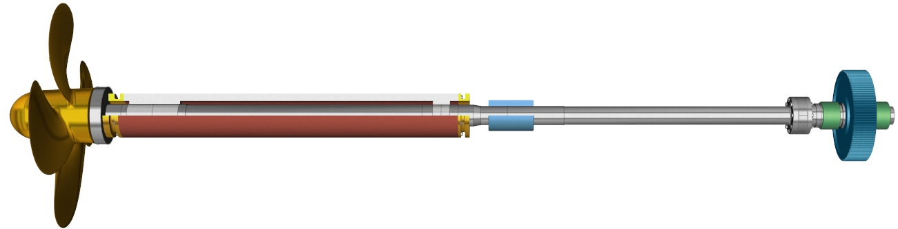
Fig.1 Two bearings shafting
 |
 |
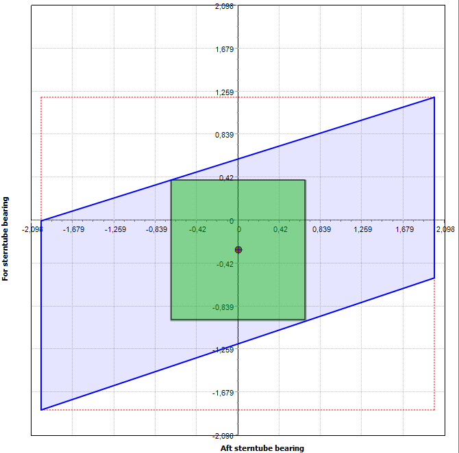 |
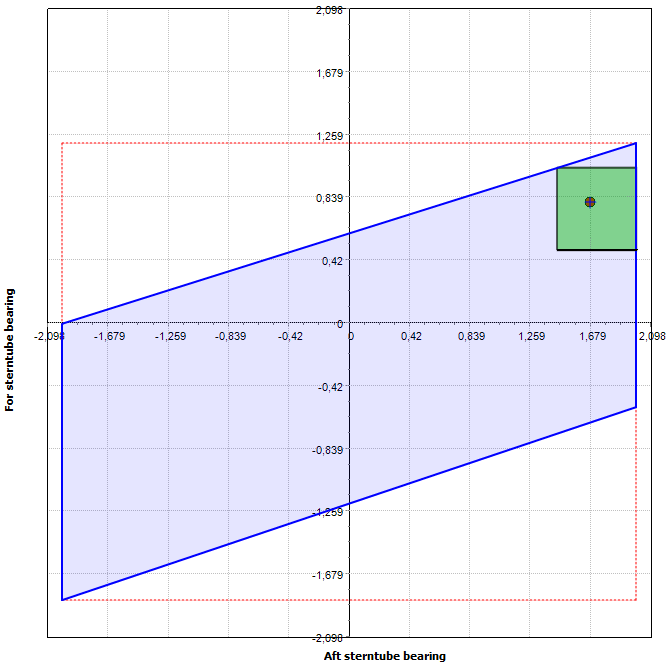
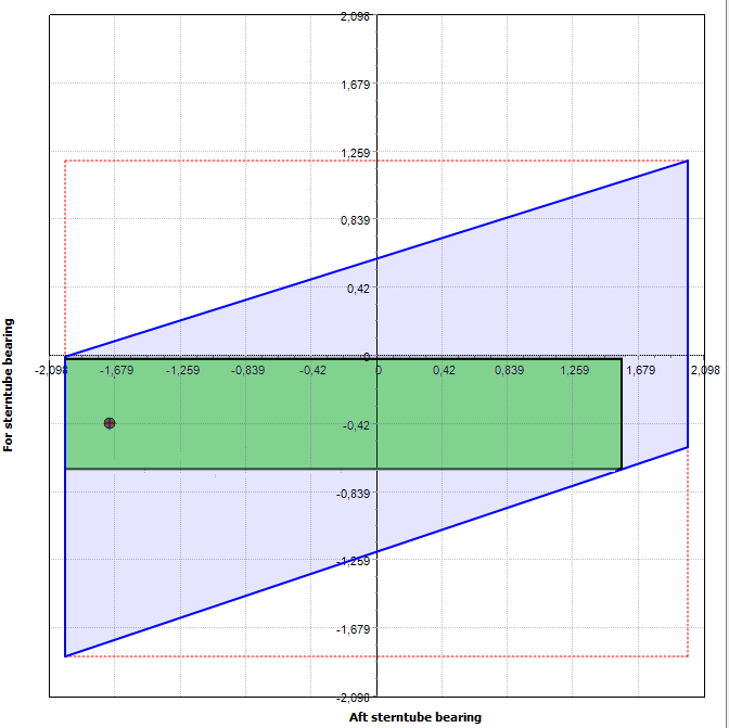
Fig.2 Three different design points, that may be selected in the 2D AOD
It is more complicated to illustrate AOD when the bearings number is greater than three (n>3). In this case, AOD is an n-dimensional polyhedron, and 2-D and 3-D sections are helpful in order to have an idea of AOD.
The visualization of AOD shows the relations of the specified acceptance criteria and how the design point is located relative to the AOD boundary.
How to select the best design point? Formally a shaft alignment designer is free to assign any point from AOD as a design point. In Fig. 2 three different acceptable points are shown. What should the criterion be used for design point selection?
For 3-bearings shafting (n=3), Fig.3, AOD is a polyhedron (Fig.4).
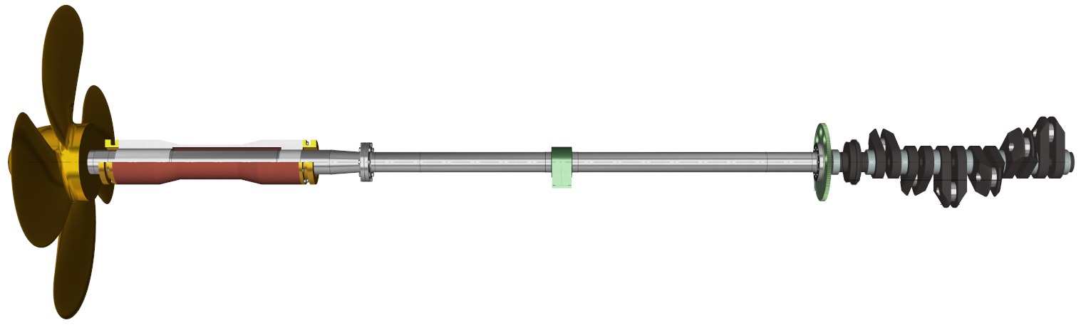
Fig.3 Three bearings shafting
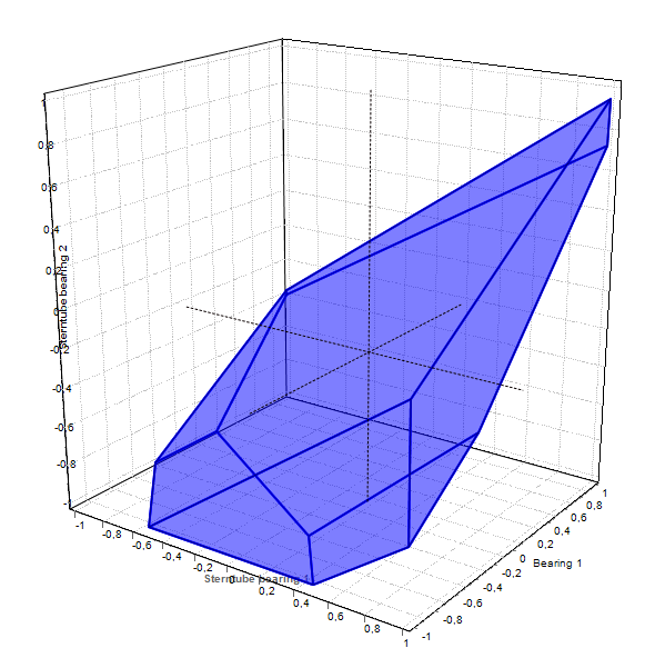
Fig.4 3D AOD
Every side of a polygon and every face of a polyhedron correspond to the specific acceptance criterion in a certain ship state.
It is more complicated to illustrate AOD when the bearings number is greater than three (n>3). In this case, AOD is an n-dimensional polyhedron, and 2-D and 3-D sections are helpful in order to have an idea of AOD.
The visualization of AOD shows the relations of the specified acceptance criteria and how the design point is located relative to the AOD boundary.
How to select the best design point? Formally a shaft alignment designer is free to assign any point from AOD as a design point. In Fig. 2 three different acceptable points are shown. What should the criterion be used for design point selection?
The most natural idea is that rational shaft alignment should provide maximum safety. It means the designer should find the shaft alignment design, which may reliably tolerate inevitable in shipyard practice mounting errors and other uncertainties. This implies that around design point must be a substantial tolerance space, formed by allowable deviations of bearing offsets.
Since all bearing offsets deviations are independent the offsets tolerance space is an n‑dimensional hyper-parallelepiped with its sides parallel to the coordinate axes and containing the design point inside: for two bearings case, it is a rectangle, for three bearings – ordinary 3D parallelepiped. In the general case, it is a hyper-parallelepiped. Any point inside tolerance hyper-parallelepiped, including boundary, satisfies all acceptance criteria. Any expansion of this hyper-parallelepiped will produce at least one hyper-parallelepiped vertex located outside of AOD.
To have shaft alignment as safe as possible it is necessary to find the best design point in the AOD which maximizes the tolerance hyper-parallelepiped. Among the three points shown in Fig. 2, point #3 is the most appropriate. The tolerance area of point #1 is too small, the tolerances of point #2 are too different (design point is not positioned near the center of the tolerance area). To find the most appropriate design point in a general case is not so simple task. Fortunately, ShaftDesigner software automates the search.
Having the design point with sufficient tolerances it is possible to generate tolerance diagrams for bearing loads, SAGs and GAPs, etc. The views of the tolerance diagrams for bearing loads and for SAG &GAP are shown in Fig. 5 and Fig. 6.
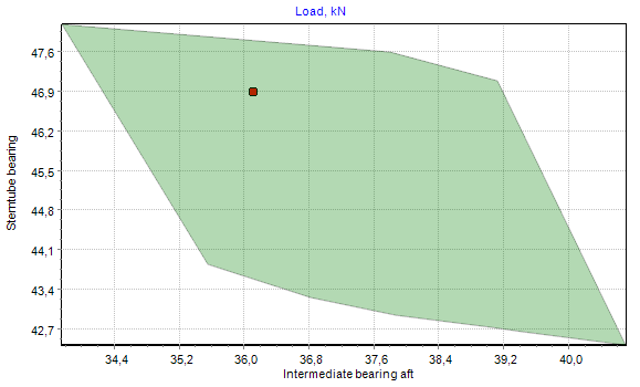
Fig. 5 Bearing loads tolerance diagram |
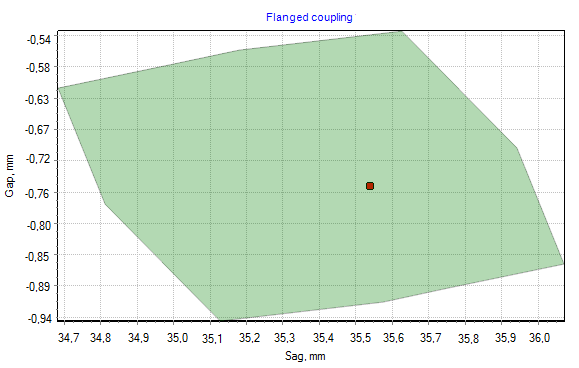
Fig. 6 SAG&GAP tolerance diagram |
It is enough to plot the measured point on the tolerance diagram to find out whether the bearing positions are acceptable or not. These days such type diagrams should become an integral part of any SAP.
The visualization of the AOD and tolerance area brought out the problems, on which one did not pay attention before. In some cases the generated AOD is extremely ‘thin’, Fig. 7.
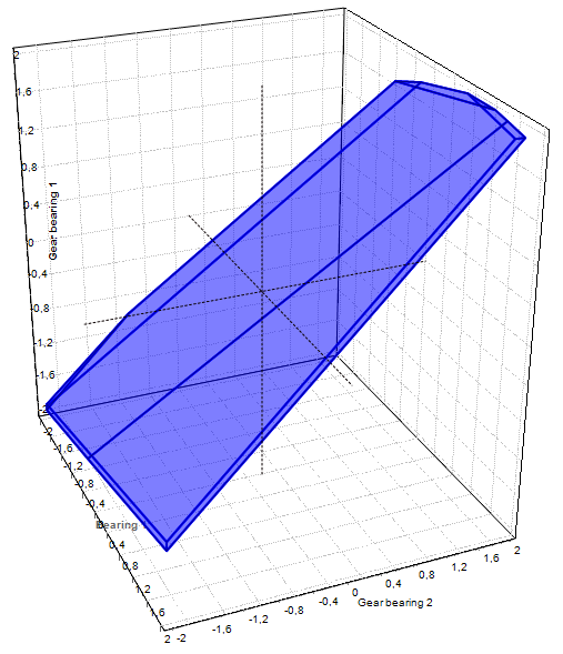
Fig. 7 ‘Thin’ AOD
It is clear that all derivative tolerances in this case also will be very small and pointless from a practical point of view.
It happens mostly for the geared installations where the gearbox manufacturer formulates very strict shaft alignment criteria which have no connection to the specific shaft line. However, it is quite possible that another arrangement of the shafting bearings may increase AOD. Therefore AOD and tolerances should be analyzed at the early stage of shafting design.
Several conclusions may be yielded from the above.
- Before to start the shaft alignment design expected ship states should be carefully and comprehensively analyzed how they may affect propulsion shafting and only after that they may be applied to shaft alignment design to obtain the safest solution.
- The design bearing offsets are to be chosen to guarantee maximum shaft alignment tolerances as far as it is possible for actual AOD space.
- Class and equipment manufacturer’s requirements for shaft alignment should be a subject to detailed study and revision. Forced whirling vibration analysis seems to be a final generalized acceptance criterion of shaft alignment design.
Application of AOD and maximum tolerance concepts in shaft alignment design may promote the enhancement of shaft alignment criteria and contribute to propulsion shafting reliability.