Y. Batrak, R. Batrak and D. Berin, Intellectual Maritime Technologies, Ukraine
SUMMARY
Computer applications for engineering design usually aim to solve certain classes of problems. As a rule it is implicitly assumed that the initial data for such calculations are well defined and unambiguous. However, in those cases where there is a set of equally acceptable input data combinations or the specific data ranges are only known, the problem arises how to set the initial data and evaluate their effect on the design parameters. To assess the impact of uncertain factors a parametric study approach is usually used. The subject of this paper is how a software package based on the parametric calculations is helping to ensure reliable and trouble-free machinery operation owing to suitable propulsion shafting alignment plan. It includes jack-up test modelling, the acceptable bearing offsets space exploring, permissible ranges of propeller hydrodynamic loads evaluation, as well as the loads ranges that can be applied to the gearbox flange.
1. INTRODUCTION
Uncertainties of different nature accompany the process of engineering design. The situation when all the input data used in some CAE system are well defined and unambiguous is very rare. Most often for some of them only order of their magnitudes, or at best the ranges of values are known. In such cases the designer faces the problem of data setting.
It is usual practice to apply a parametric study to assess the impact of uncertain factors. The question is to what extent this process is labour-intensive and time-consuming especially if the designer is forced use it regularly.
The propulsion machinery production design includes development of the shaft alignment plan based on safe initial spatial positions of the bearings. The shaft alignment plan consists of technological parameters, required by certain shaft alignment techniques, that assumed to be used during propulsion system construction or renovation.
The subject of this paper is how a software package based on the parametric calculations is helping to design the optimal propulsion shafting alignment plan to ensure reliable and trouble-free machinery operation.
Most of the shipyards, in spite of existing modern strain gauges shaft alignment technique, still use jack-up test to verify the correspondence of bearing positions in the vertical plane to the shaft alignment plan supplied by consulting company or propulsion shafting manufacturer. Very often field engineers cannot adjust the bearings to fulfil the requirements stated in the shaft alignment plan. One of the possible reasons is a discrepancy between the actual bearing reaction point of the cylindrical finite length bearing and the bearing positions used in the shaft alignment plan design. Parametric calculation enables visualization of bearing point position during jack-up test and estimate bearing loads more precisely.
It is well known that there is an infinite set of acceptable alignment plans, therefore a shaft designer must have a tool for an informed choice of the most suitable. For this the acceptable bearing offsets domain is to be visualized to see the domain boundaries caused by the acceptance criteria and determine a shaft alignment plan with maximal safe shaft alignment tolerance. The parametric calculations give the insight to the acceptable offsets domain.
Propeller hydrodynamic loads affect the alignment plan very much. Since the trouble free operation must be ensured in all operating conditions the propeller loads should be set as correctly as possible. At the same time despite new CFD methods the propeller loads are still not be firmly predicted: different methods bring substantially different results. Fortunately the shaft designer, if he does not know load magnitude exactly, may be satisfied by the fact that certain degree of propeller loads variations do not violate the acceptance criteria. This fact also can be revealed on the base of parametric studies.
The gear box is a shafting equipment most sensitive to the shaft alignment. The gear box manufacturers, trying to provide more safe conditions for operation of their product, declare very strict shaft alignment acceptance criteria. Sometimes they are so strict that they may be not compatible with the shafting design and propeller loads. Unfortunately shaft designer without a special tool cannot solve for himself/herself the dilemma: does the acceptable shaft alignment plan not exist, or is he/she is not enough qualified to find it. A parametric study tool is helpful in this case too.
2. JACK-UP TEST SIMULATION
The shaft alignment procedure usually is finalized by verification of bearing positions. The jack-up test is most commonly used for this purpose. It is an indirect method. Bearing loads from the shaft alignment plan are to be compared with the measured jack loads multiplied by the correction factor determined in the shaft alignment design.
There are several bearing models used in the shaft alignment design: simple support, bilateral support, ring support and finite length cylindrical support [1]. As a rule simple support model (point support) is predominantly applied. The shaft designers, using this approach, usually face the problem of bearing point assignment, because the real bearings stern tube are of finite length.
The ShaftDesigner software provides all types of supports models, including finite length cylindrical support. So it enables direct simulation of the jack-up test in shaft alignment design. The simulation function is implemented as a parametric study with a vertical load applied at the jack position as a parameter.
The shafting depicted in Fig. 1 has the jack installed near the forward stern tube bearing. The shaft travel during jack-up test and the bearing load point travel of the aft and forward stern tube bearings are shown in Fig. 2-4 correspondingly. The position of the load point is measured from the aft edge of the bush. The events during jack-up test, listed in Table 1, are useful for interpretation of the graphs.
It is clear that test bearing point is not constant during jack-up test. The field engineers must have the prearranged most realistic theoretical jack-up test graph to compare with the measured one.
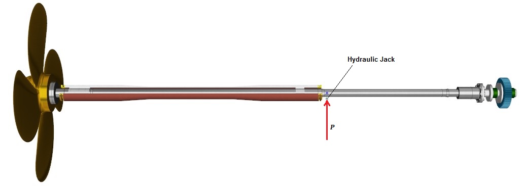
Figure 1: Shafting model with jack installed
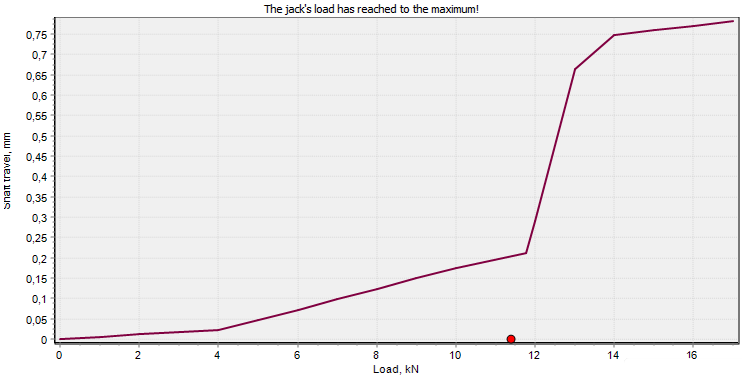
Figure 2: Shaft travel during jack-up test
Table 1
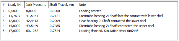
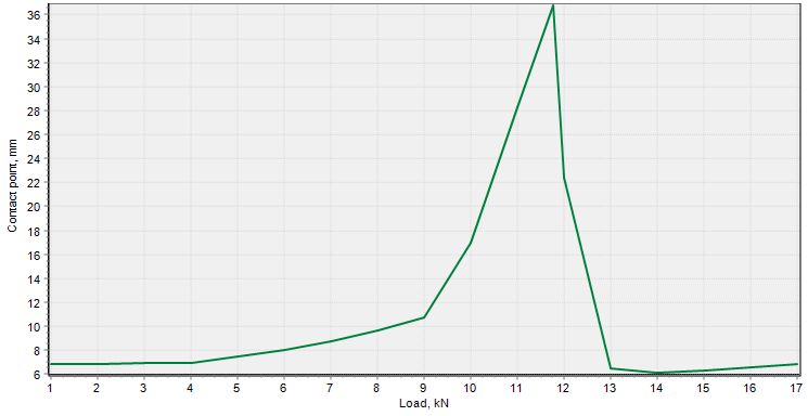
Figure 3: Load point position travel of the aft stern tube bearing
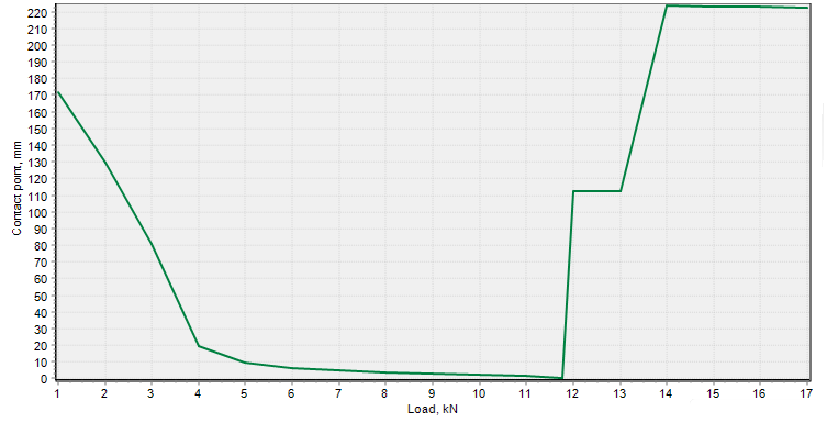
Figure 4: Load point position travel of the forward stern tube bearing
3. BEARING OFFSETS SPACE EXPLORING
Optimal spatial positions of the bearings are the base of shafting alignment plan design. Bearing spatial position is a set of four parameters: two linear offsets (vertical and horizontal) of the bearing bush centre point and two angular offsets of the bush axis in the vertical and horizontal plane correspondingly. The offsets are measured relative to a fixed reference line.
Linear bearing offsets in the vertical plane are most crucial for shafting therefore the shaft designers primarily are focused on the determination of these values. Unfortunately there is no a definite unambiguous procedure for setting of bearing offsets. It is still kind of art but the task may be simplified if the designer has an imagine of the acceptable offset domain.
Vertical bearing offsets must satisfy the shaft alignment acceptance criteria. The acceptance criteria are a set of requirements of the Classification Societies and equipment manufacturers to the shaft bending characteristics. Since the acceptance criteria have the form of inequalities the acceptable bearing offsets form a domain in a multidimensional space. As a result the shaft designers face the problem how to choose one certain offset point from the infinite set of the acceptable.
To solve this problem the visualisation of the acceptable offsets domain and some procedure for evaluation of the point choice are required. This paper concerns the visualisation of the domain only.
The problem of visualisation has a simple solution when the bearings are modelled as simple supports. In this case all inequalities of the acceptance criteria are of linear type and can be presented as hyper planes. The acceptable offsets domain (if it exists!) has a view of n-dimensional polyhedron, where n is number of the supports to be adjusted during the shaft alignment procedure.
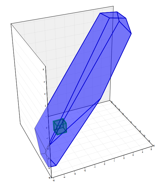
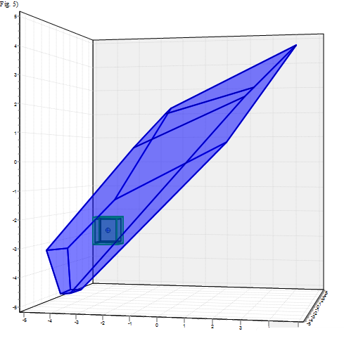
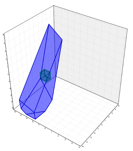
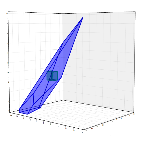
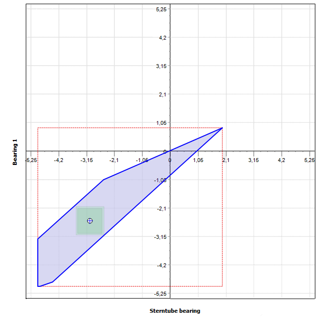
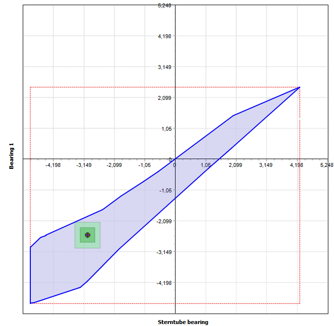
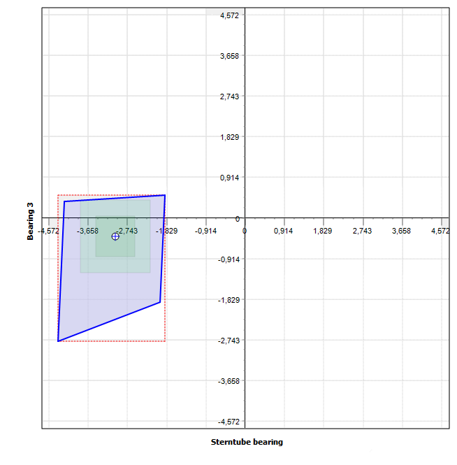
The domain polyhedron has a geometrical presentation if n ≤ 3. To build the polyhedron standard procedure can be applied [2]. When n > 3 the domain may be explored using 3-D or 2D sections, corresponding to certain combinations of the bearings. The 3D sections of the acceptable offsets polyhedron for the shafting depicted in Fig. 5 are shown in the Fig. 7. In this case bearings are modelled as simple supports, Fig. 6.
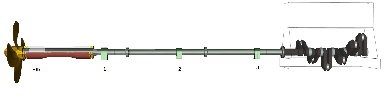
Figure 5: Shafting with four bearings
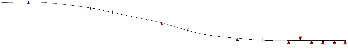
Figure 6: Bearings are modelled as simple supports
Stern tube Bearing – Bearing 1- Bearing 2 |
Stern tube bearing-Bearing 1- Bearing 3 |
Stern tube bearing – Bearing 2 – Bearing 3 |
Bearing 1- Bearing 2 – Bearing 3 |
Figure 7: 3D sections of 4-dimensional polyhedron of the acceptable offsets
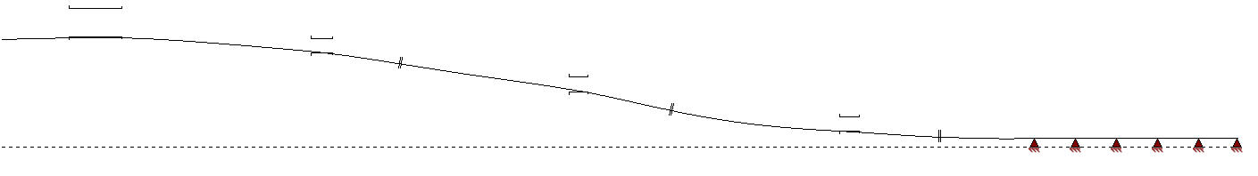
Figure 8: Bearings modelled as finite length cylindrical supports
| Bearings modelled as simple supports | Bearings modelled as finite length cylindrical supports |
 |
 |
 |
 |
 |
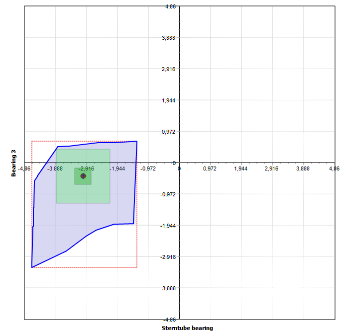 |
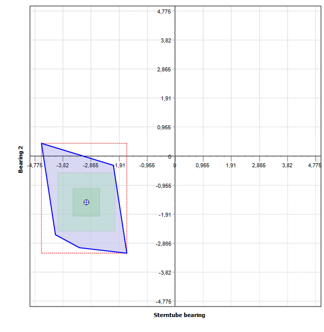
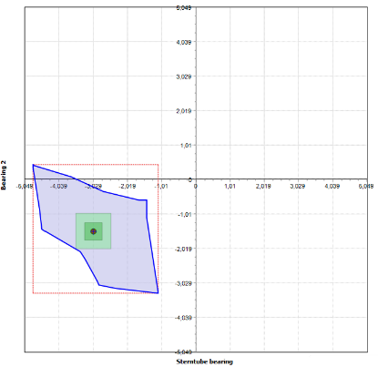
Figure 9: Some 2D-sections of acceptable offset domain
When bearings are modelled using more realistic approach of finite length cylindrical support (see Fig. 8) the problem becomes nonlinear and the acceptable offset domain cannot be built by a regular mathematical method. Parametric calculation is suitable in this case.
Because of the problem of nonlinearity a 3D geometrical presentation of the acceptable offset domain cannot be built within a reasonable time. In this case maximum 2D sections of the domain body may be visualized. In Fig. 9 three corresponding 2D sections of the acceptable offset domain obtained for the shafting (Fig. 5) using two different models of the bearings are compared.
It should be noted that nonlinearity may be caused not only by finite length of the bearing but by the presence of diametric clearance. If the shafting roller bearings are installed they may bear positive as well as negative load. This leads to the fact that acceptable offset domain becomes multiply connected. The shafting depicted in Fig. 1 has three-connected acceptable offset domain, Fig. 10 (simple supports model is used).
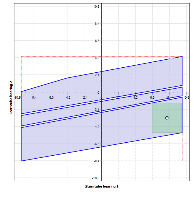
Figure 10: Three-connected acceptable offsets domain
Visualization of the acceptable offsets domain facilitates search of the point which provides maximum shaft alignment tolerance. The search may be done manually or automatically, ShaftDesigner software has a special function for this. The tolerance zones (local and global) are shown in Fig. 9-10 by green colours.
It should not be assumed that construction of the acceptable offsets domain can be done without problems in any case. Sometimes formulations of the acceptance criteria are contradictive, and acceptable offset domain does not exist at all or degenerates into a very tiny set. This requires special tools to reveal the problem. One of the tools for the case of geared installations is discussed below. The procedure of parametric calculations for construction of a 2D section of the acceptable offset domain is as the following. In the first step one point in the acceptable offsets domain is to be found. It is quite possible that current offset point (offsets assigned to the bearings) or zero offset point is acceptable. If any of these points is not acceptable a special procedure is used to find the acceptable point. At this moment all n bearing offsets are treated as variable parameters.
In the second step n-2 offsets are fixed and the rest two should be chosen to present the acceptable offsets domain section. In the third step the section boundary point is searched using simple dichotomy. At this moment only one offset from two is treated as a parameter. After the boundary point is found both offsets become parameters and the last forth step starts. At this stage all points of the section boundary are to be found with prescribed accuracy to form a continuous line.
Each point inside of the acceptable offset domain can be associated with a maximal ndimensional hypercube that can be inscribed in the domain having this point as the centre of hypercube. Half of the hypercube side length defines the safe alignment tolerance. Safe alignment tolerance means the maximum deviation δ of the linear bearing offsets that keeps the acceptance criteria is not violated. This value is the same for all bearings.
4. PROPELLER LOADS VALIDATION
Propeller hydrodynamic loads affect alignment plan very much especially those acting in the vertical plane. Unfortunately there is no single universally recognized method of propeller load computation for the purpose of shaft alignment calculations. The known methods for hydrodynamic loads calculation have shown a great scatter of results [3].
It is no wonder that most of Classification Societies rules not always provide recommendations for this matter. From the other side shaft designers very often have no the calculation tools and/or the specific data (such as wake flow parameters) to compute propeller hydrodynamic loads using specialized software. For this reason various approximate estimations are popular among shaft designer, especially at the early design stage. In our practice for one screw ships we use the following recommendations that were obtained by the statistical processing of propeller loads for 20 ships:
Table 1
| Load | Mean value, % | Deviation (±),% |
| Vertical force, Py | 2,0 | 1,5 |
| Horizontal force, Pz | -5.0 | 2.0 |
| Horizontal moment, My | 23,0 | 4,5 |
| Vertical moment, Mz | -35.0 | 10.0 |
In the Table 1 the hydrodynamic forces and moments and their deviations are presented as percentages of the mean thrust Px and mean torque Mx correspondingly. Positive load directions are shown in Fig. 11.
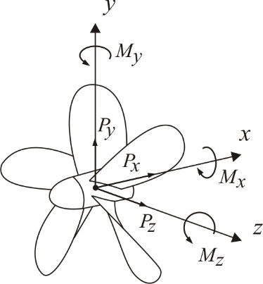
Figure 11: Positive propeller load
The shaft designer to take care for safety margin and exercise some caution when choosing the shaft alignment plan. The shaft designer wants to be sure that in spite of certain uncertainty of propeller load values the acceptance criteria will not be violated in any operating condition.
There are propeller hydrodynamic loads combinations for which shaft alignment acceptance criteria are satisfied and combinations where they are not satisfied. So some acceptable propeller loads domain must exist. The shaft designer should know the boundary of this domain to validate used propeller load and evaluate the safe margins.
When the loads in the vertical plane are only explored, the acceptable propeller loads domain is 2D and can be easily build on the base of parametric calculations. Samples of propeller loads domain constructed for the shafting (Fig. 12) are depicted on Fig. 14-15. There
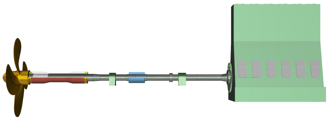
Figure 12: Directly coupled installation with two states |
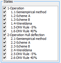
Figure 13: The methods used for propeller loads determination |
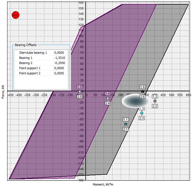
Figure 14: Not all loads are within the acceptable domain
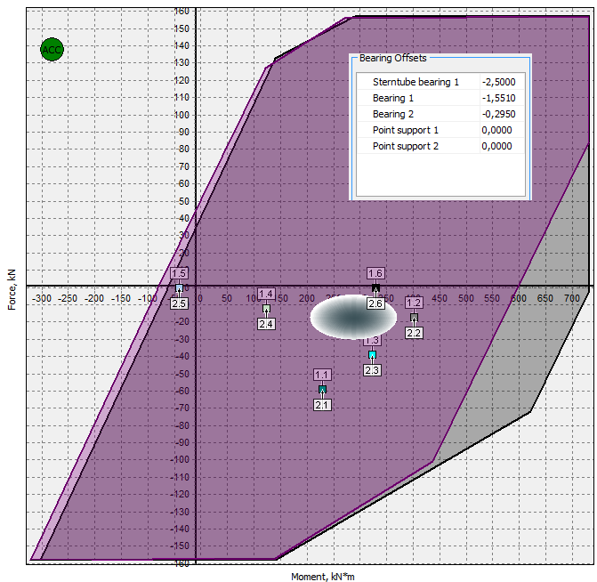
Figure 15: Positions of the propeller load points after bearing offsets adjustment
are two acceptable domains of propeller loads accordingly to the number of shafting states.
As can be seen from Fig. 14 not all propeller loads estimated by different methods (see Fig. 13) are within the acceptable propeller loads domains. Elliptical area is the set of the points (Py, Mz), obtained by the proposed statistics, Table 1. For shaft designers it is an annoying fact that all the loads in Fig. 14 are concentrated near the boundary of the acceptable areas and outside of the domains. Therefore the bearing offsets used for domains construction must be rejected. After adjustment of the bearing offsets the area of the acceptable propeller loads domains increased, Fig. 15. All of the estimated loads points belong now to the acceptable loads domains and most of the load are concentrated at the centres of the domains, providing sufficient safe margins.
It is clear that the acceptable propeller loads domain shape and position depends not only on the acceptance criteria set but also on the actual alignment plan. Using parametric calculations for evaluation of the propeller loads the shaft designer may be more confident in the shaft alignment plan.
Algorithm of the acceptable propeller loads domain construction is the same as for the section of the acceptable offset domain (see above). As the parameters this time the vertical force Py and the vertical moment Mz on the propeller are used.
4. SHAFTING/GEAR BOX CONFLICT
Gear box is directly coupled with shafting therefore the shear forces and bending moments, coming from the shafting side, affect the gear box output shaft bearings.
The gear box manufacturers, trying to provide more safe conditions for operation of their product, sometimes declare very strict shaft alignment acceptance criteria.
They may be not compatible with the shaft line design and the ship operating conditions and the shaft designer may spent a lot of efforts trying to find the acceptable shaft alignment plan.
It is because in a such a case the acceptable offset domain is very small or even does not exist. For the same reason the optimization procedures also do not work and to find the solution automatically is impossible.
The acceptance criteria for gear box bearings as a rule must be satisfied in several operating conditions, for example:
- Cold static.
- Warm static.
- 100% MCR, cold
- 100% MCR, warm
It should be noted that acceptance criteria in the static conditions may differ from those for running conditions. In running conditions only the additional bearing loads caused exclusively by alignment forces coming from the shafting side may be restricted.
To be sure that the appropriate shaft alignment plan can (or cannot) be found and to avoid time wasting for non-productive calculations a special procedure for checking of the gearbox and shafting compatibility should be used.
The diagrams of acceptable bending moment and the shear force at the gearbox flange obtained by the parametric calculations for the model Fig. 16 are shown in the diagram Fig. 17.
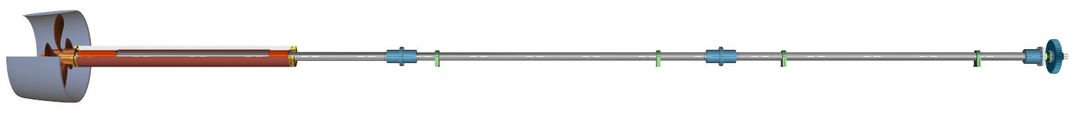
Figure 16: The shafting conflicting with gear box
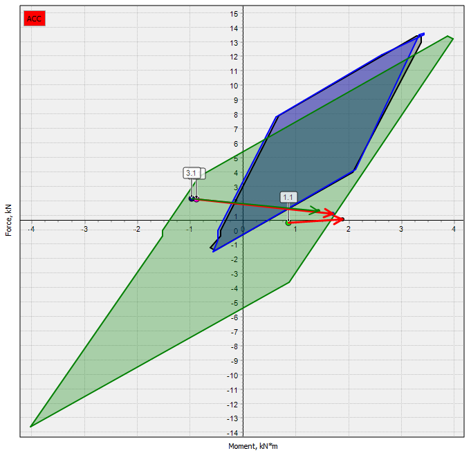
Figure 17: The gear box acceptance criteria are not satisfied for current shaft alignment plan in two ship states |
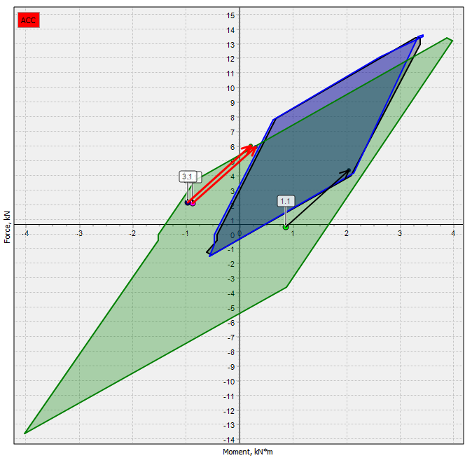
Figure 18: There is no shaft alignment plan to satisfy gear box acceptance criteria |
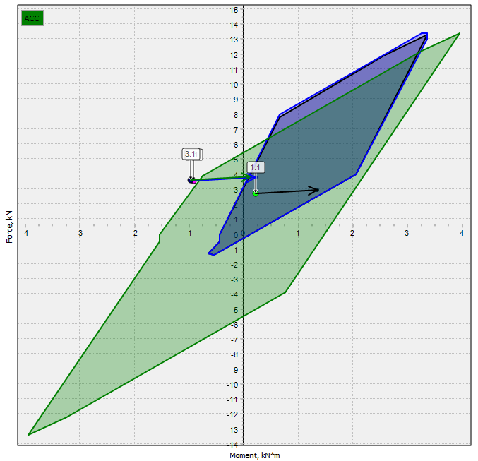
Figure 19 For modified shafting design the gear box acceptance criteria are satisfied
The acceptable shaft alignment plan exists (or may exist) if the vectors’ ends are inside the correspondent acceptable area. As can be seen from the diagram (Fig. 17) in two ship states of three the loads on the gear box flange (the ends of the vectors) are outside of the acceptable domains. The starting points of the vectors indicate gear box flange loads at zero offsets.
All further attempts to place vectors’ ends inside of the acceptable domains by dragging vectors’ ends for this project were unsuccessful. One of the attempts is shown in Fig. 18.
The distance between points 1.1 and 3.1 is so great that there is no positions of vectors’ ends (bearing offsets by other words) when all the points would be within the acceptable domains. It should be concluded that the acceptance criteria are not compatible with the shaft line design and operating conditions.
After the bearing closest to the gearbox was shifted to the aft by 500 mm all the acceptance criteria at the same shaft alignment plan were satisfied, Fig 19. Thus the parametric calculations may help to find the appropriate shafting design compatible with gear box manufacturer shaft alignment acceptance criteria.
5. CONCLUSIONS
Parametric calculations are useful means to estimate the effect of different uncertainties, that are inevitable in the shafting design process. They help to construct some graphs to facilitate the decision making process. In this paper was demonstrated how the parametric calculations may be used for jack-up test simulation, construction of acceptable bearing offsets domain, propeller loads validation and analysing of gear box and shafting compatibility.
To solve every of the above listed problems, special functions were developed. Jack load, bearing offsets, hydrodynamic loads onto propeller and loads onto gear box flange were used as parameters. But it is quite possible that for a shaft designer the need arises for the parametric study of other, not predefined problems. Being aware of the great benefits of the parametric calculations the software development team made a decision to provide in the future an universal function that enable the user to arrange his own parametric study independently.
6. ACKNOWLEDGEMENTS
We express special thanks to Geoffrey de Vlaam and Bram Hooghart SKF Solution Factory – Marine Services for their contributions and feedback.
7. REFERENCES
- BATRAK, Y., BATRAK, R. and BERIN, D., ‘Computer Application for Shaft Alignment Design’, Proceedings of the International Conference on Computer Application in Shipbuilding, 2013.
- MOTZKIN, T. S., RAIFFA, H., THOMPSON, G. L. and THRALL, R. M. ‘The double description method’. Contributions to the theory of games. Annals of Mathematics Studies (volume 2, number 28). Princeton, N. J.: Princeton University Press, 1953. pp. 51–73.
- BATRAK, Y. and SHESTOPAL, V., ‘Propeller Hydrodynamic Loads in Relation to propulsion Shaft Alignment and Vibration Calculations’, Propellers / Shafting Symposium, Norfolk VA, 2012.
8. AUTHORS BIOGRAPHY
Dr. Yuriy Batrak Ph.D holds the current position of consultant at Intellectual Maritime Technologies company. He is responsible for the formulation of the software development trends. His previous experience includes developing of ShaftMaster software for shaft alignment calculations, hull structures tests at the shipyards, sea ship trials measurements, lectures on computer science and discrete mathematics at the university.
Roman Batrak holds the current position of project manager at Intellectual Maritime Technologies company. He is responsible for general managing of software development, application programming, automatic testing and software protection. His previous experience includes development of ShaftMaster software, the software system for ship traffic control in channels, engine room simulator development.
Dmytro Berin holds the current position of programmer at Intellectual Maritime Technologies company. He is responsible for optimization procedures programming, programming of GUI and calculation results documentation. His previous experience includes development of the software system for ship traffic control in channels, engine room simulator development.