Yuriy Batrak
Intellectual Maritime Technologies,
19-g/12 Krylova str., Mykolaiv 54038, Ukraine
yuriy.batrak@marine-software.com
Abstract
Since analysis of shafting transient torsional vibrations caused by ice impacts became mandatory, numerous modelling-based calculations have been carried out for ships sailing under ice class. However, the calculation results still do not allow to obtain general conclusions from the shafting response in ice conditions. The main reasons for this could be summarized as follows. First of all, the different tools in use for the prediction of transient vibrations make the comparison of analysis results rather difficult. Secondly, some simplifications about the response of the propulsion system in ice conditions are to be made because the consideration and addressing of the complex nature of a propulsion system in practical design are impossible for many reasons. Thirdly, various underlying uncertainties in the input data put a shaft designer in a situation in which he needs to make a decision. This paper is an attempt to make some contributions to the presentation and analysis of the propulsion shafting torsional vibration induced by propeller-ice interaction. Two practical examples are considered: for a polar class ship with a direct coupled diesel engine and another one for the case of a geared propulsion unit. Some uncertainties in data setting concerning of the design torques are considered and assessed.
INTRODUCTION
Numerous calculation procedures were developed since 2011 when calculations of ice class ship propulsion shafting transient torsional vibrations caused by propeller-ice impacts became mandatory. Unfortunately detailed presentations of the analysis and issues of calculation are still not published. This paper is an attempt to make some contribution to fill the gap based on the experience gained with ShaftDesigner software [1].
Various underlying uncertainties in the prediction of the ice induced peak torque and peak-to-peak torque (such as propeller speed drop during ice milling, added inertia of a propeller, propeller damping and others) hinder the adoption of design decisions. Lack of the comprehensive studies of these really complex issues in current situation forced to look for approximated influences of these uncertainties.
DATA SETTING ISSUES
Inertia
During the ice milling and crushing process the propeller vibrates in a mixture of water and ice. The external forces, proportional to propeller acceleration, are increasing significantly and can no longer be considered only as a conventional entrained water inertia. Nevertheless there is a recommendation to keep the propeller added inertia as for open-water operation [4]
Damping
Propeller damping characteristics in ice induced torsional vibration may change significantly due to blocked flow and/or cavitation effect. But the simplest viscous damping model is still used.
Flexible couplings manufacturers usually provide damping parameters applicable to a frequencydomain analysis. The simplest recommendation in these circumstances is to set the damping using the major excitation frequency of the ice related excitation load [4].
Stiffness
Dynamic stiffness of the flexible couplings in most cases also is defined depending on excitation frequency. This is a challenge how to set it in the analysis of torsional vibration induced by propeller-ice interaction.
Excitation
Propeller ice loads are the result of a combination of several different phenomena of contact and non-contact nature. Contact propeller-ice interaction is related to the ice impact and ice milling. Non-contact propeller-ice interaction is related to hydrodynamics defined by the blockage effects, proximity effects, and cavitation.
The Class Rules [5] prescribe that propeller loads of the ice class ships must consist of two components: ice milling torque and open-water hydrodynamic torque. Such approach simplifies the analysis very much, and it would be great if this approach fully meets the needs of reliable shafting design. Currently this remains unknown.
Furthermore the characteristics of transient torsional vibration caused by ice impacts may also depend on the initial state of the propulsion system at the moment immediately preceding to the first ice hit.
CASE STUDIES
In order to analyze torsional vibrations caused by propeller-ice interaction, there is a need to answer several questions, which result from the physics of the phenomena but are not in the scope of regulatory documents:
- how does the propeller inertia moment added during propeller-ice interaction affects the calculation results?
- whether the accuracy of damping setting is important for transient torsional vibration of the propulsion shafting induced by ice impacts?
- how to overcome the indeterminate engine speed drop?
- is the initial phase of the milling process critical for shafting response?
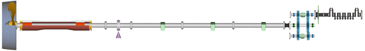
Next, the answers to these questions for projects Case-1, and Case-2 Fig. 1, 2 are considered. For the property of the projects see Appendix.

Ice class GL E4 (IA Super)
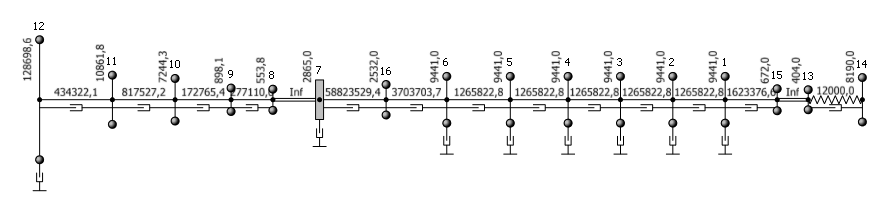
Fig. 1 – Propulsion shafting and mass-elastic system of the ship Case-1
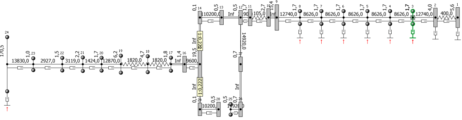
Ice class LR 1C
Fig. 2 – Propulsion shafting and mass-elastic system the ship Case-2
Peak and peak-to-peak torque
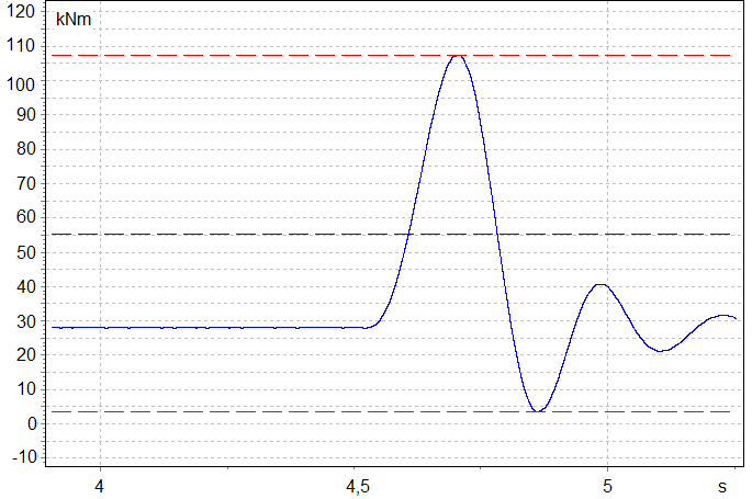
| Two main design characteristics for each shafting element are to be calculated in the analysis of transient torsional vibration induced by ice impacts, which are peak torque (PT) and peak-to-peak torque (PTPT), Fig. 3. Maximum torques in the propeller shaft of the ship Case-1 and Case2 are shown in the Fig. 4, 5. Open water alternating torque amplitudes for the Case-1 are shown by the dotted line. The amplitudes |
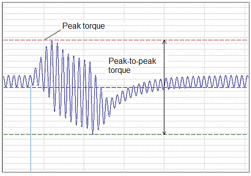
Fig. 3 – PT and PTPP definitions |
| of the alternating torque in the Case-2 are very low compared to the ice induced torque and are not shown.
The estimation of ice induced components of the PT for both projects are presented in Table 1. Besides nominal speeds Table 1 includes the critical speeds. It is obvious that relative contributions of ice load are quite different. Contribution of ice load in design torque is more significant for the Case-2. |
|
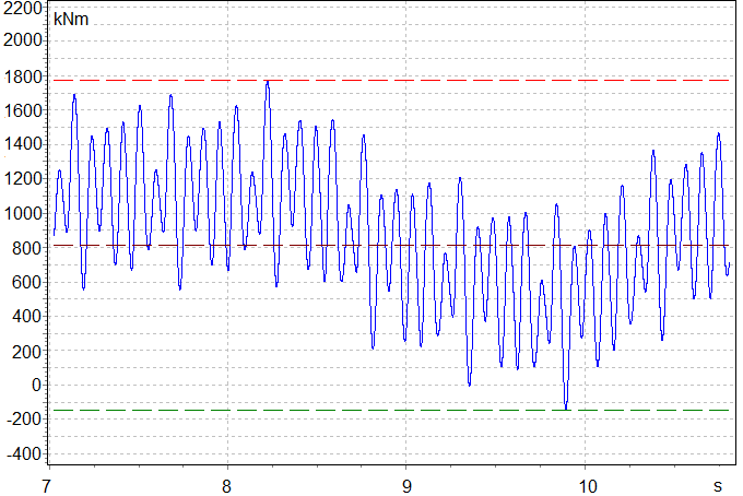
The PT of both projects increase with the engine speed increasing, (Fig. 4, 5). For the Case-1 a major vibration component of the PT at all engine speeds is the open water alternating torque, while in the Case-2 it is the ice induced component (see Table 1). The difference between Case-1 and Case2 PT responses can be seen from the time waveforms Fig. 6, 7.
The PTPT in the Case-1 has an evident maximum (6th order resonance). The PTPT in the Case-2 grows simultaneously with the PT because the open water component does not influence the result.
It should be noted that the maximum PT and PTPT in the shafting elements may occur at different Regulatory Loads (there are three Cases of prescribed loads in Classification Societies rules) depending on shaft speed.
 |
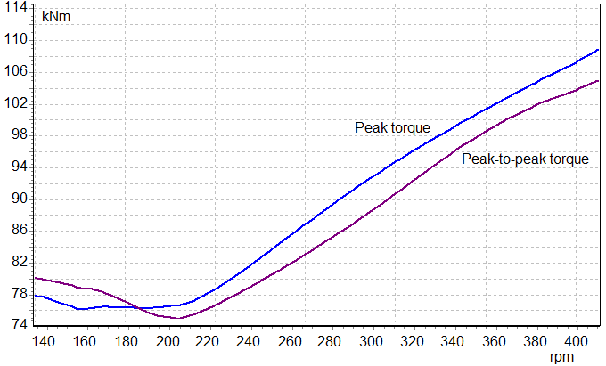 |
| Fig. 4 – Case-1: PT and PTPT | Fig. 5 -Case-2: PT and PTPT |
Table 1 Components of the propeller shaft peak torque
| Engine speed, rpm |
Mean torque, kNm |
Open-water alternating torque, kNm |
Peak torque, kNm |
Estimate of ice induced component, kNm |
|
| Case-1 | 68 ν=6 | 425 | ± 1020 | 1698 | 253 |
| 86 ν=1Z | 680 | ± 770 | 1670 | 220 | |
| 111 nom | 1135 | ± 635 | 1853 | 83,0 | |
| Case-2 | 915 ν=1,5 | 7,25 | ± 0,24 | 76,9 | 69,5 |
| 1300 ν=1Z | 14,7 | ± 0,19 | 91,1 | 76,4 | |
| 1800 nom | 28,0 | ± 0,12 | 107,4 | 79,3 |
 |
 |
| Fig. 6 – Case-1: PT time waveform for propeller shaft | Fig. 7- Case-2: PT time waveform for propeller shaft |
Engine speed drop and MIP rise
The discrepancy between measured and predicted speed drop is shown in the paper [3], where the measured speed drop is significantly less than the predicted one. With the right approach, engine speed drop and corresponding mean indicating pressure (MIP) rise should be found out by propulsion system simulation [2]. This simulation is rather complicated and unjustifiably expensive because besides of a propulsion shafting the other components such as speed governor, load governor, turbocharger, turbine receiver, receiver of compressor are to be taken into consideration. Moreover most of the input data for such simulation are not available for a shaft designer. For this reason in shafting design a parametric study approach may be used instead of accurate simulation.
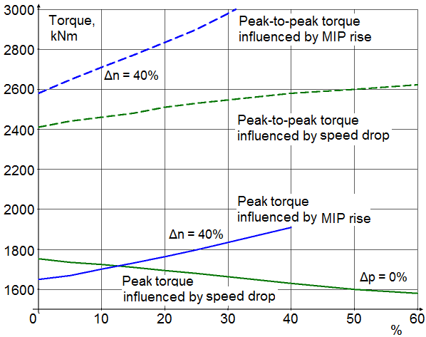
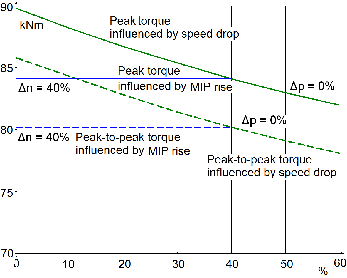
Examples of parametric studies results are shown in the Fig. 8, 9. Two families of curves are presented. The short curves show the dependence of PT and PTPT in the propeller shaft on the MIP rise when the speed drop is fixed to Δn=40 %, and the long curves show the dependencies of the design parameters on the speed drop when the MIP rise is set to zero Δp=0 %.
 |
 |
| Fig. 8 – Propeller shaft Case-1: Speed drop and MIP rise influence | Fig. 9 – Propeller shaft Case-2: Speed drop and MIP rise influence |
As it can be seen for the Case-1 MIP rise affects the design parameters more than speed drop because of the great role of open-water response. Project Case-2 has engine and propeller separated by the flexible couplings so design parameters in the propeller shaft practically are not affected by the MIP rise. Speed drop in Case-2 has a greater impact. In spite of such significant ranges of the speed drop and MIP rise variation, the design parameters changes only about 10 %.
Table 2 Influence of propeller added inertia increasing in ice conditions
| Inertia in ice
In open water |
Peak torque |
Peak-peak- torque |
Peak torque |
Peak-peak- torque |
||
| Case-1 | 1 | 1 | 1 | Case-2 | 1 | 1 |
| 1.5 | 0,998 | 0,971 | 1,008 | 1,048 | ||
| 2,0 | 0,993 | 0,936 | 1,016 | 1,086 | ||
| 2,5 | 0,983 | 0,896 | 1,024 | 1,118 |
Propeller added inertia
The results of the propeller added inertia parametric studies are shown in the Table 2 where the influences of the propeller added inertia on the PT and PTPT in the propeller shaft at the nominal speed are shown. Parameters values ‘1’ corresponds to the entrained water inertia in open-water condition.
Propeller added inertia affects PT and PTPT in the propeller shafts of the Case-1 and Case-2 differently. For the “heavy” shafting of the Case-1 design parameters are decreasing while for the “light” shafting of Case-2, on the contrary, are increasing. With such a large assumed increase of added propeller inertia, the variations of the design parameters do not exceed 12 %.
Propeller damping study
Propeller damping is yet another uncertain input parameter the influence of which has been studied for both projects Case-1 and Case-2. It is recommended for open-water conditions to take Archer number from the range 25-35. For ice milling conditions, there is recommendation [4] to use the Archer number equal to 20. The dependence of the design parameters on the variation of Archer number relative to recommended value 20 is shown in the Table 3.
Table 3 Influence of propeller damping variation in ice conditions
| Archer numb20 | Peak torque |
Peak-peak- torque |
Peak torque |
Peak-peak- torque |
||
| Case-1 | 0,50 | 1,027 | 1,011 | Case-2 | 1,024 | 1,034 |
| 0,75 | 1,013 | 1,006 | 1,006 | 1,017 | ||
| 1 | 1 | 1 | 1 | 1 | ||
| 1,25 | 0,988 | 0,990 | 0,988 | 0,983 | ||
| 1,5 | 0,977 | 0,984 | 0,978 | 0,967 |
For both projects, the increase of propeller damping results in the design parameters decrease. It means that propeller damping decreases torques. Deviations from the Archer number 20 in both directions may affect the design parameters not more than 5 %. DNV/GL recommendation leads to increasing of the design parameters and may be explained by the desire to get conservative, i.e. safer results in the uncertain conditions.
Impact phase study
The open-water alternating torques in shaft elements are in some phase before the first ice hit event happens. Series of calculations with variation of the first hit event time were performed to study how the first hit phase affects the design parameters. Neglecting of the phase selection for the projects with significant open-water alternating torque may overestimate the design parameters value up to 12 %.
SUMMARY
Application of the parametric study to the design parameters, namely peak torque and peak-to-peak torque in ice induced torsional vibration led to the following conclusions:
- The response on propeller-ice interaction in a great extent depends on individual dynamic properties of the shafting. There are no universal recommendations and predictions.
- During propeller-ice interaction the conventional (open-water) excitations can make a major contribution into design parameters, especially in resonance conditions, although in other cases the ice torque is a determining factor.
- The speed drop and MIP rise, which express the engine response on the propeller-ice interaction, affects the design parameters of the propeller shaft of the projects under consideration up to 10 %.
- Different projects may responses on the propeller ice added inertia differently increasing or decreasing propeller shaft design parameters. On the whole, changes not exceed 12 %.
- DNV recommendation to set the Archer number in ice induced torsional vibration analysis to 20 is quite reasonable.
- Wrong selection of the ice impact phase may lead to overestimation of the design parameters up to 12 % when open-water alternating torque is significant.
REFERENCES
[1] Batrak, Yuriy. 2009, New CAE Package for Propulsion Train Calculations. ICCAS papers, September Shanghai, v II, 187-192. [2] Batrak, Yuriy and Serdjuchenko, Anatoliy and Tarasenko, Alexander. Calculation of Torsional Vibration Responses in Propulsion Shafting System Caused by Ice Impacts. Torsional Vibration Symposium, 2014, Paper No 21, Salzburg, Austria. [3] Dahler, Geir and Stubbs John T. and Norhamo, Lasse. Propulsion in ice – Big ships. SNAME, Proceedings ICETECH 2010 Conference, Paper No. ICETECH 10-133-R0, (2010). [4] DNV Ice strengthening of propulsion machinery. 2011Classification Notes No 51.1, January. [5] DNV Rotating Machinery, Power Transmission. Rules for Classification of Ships/High Speed, Light Craft and Naval Surface Craft Part 4 Chapter 4, January 2013,1. DNV Ships for Navigation in Ice. Rules for Classification of ships, Part 5 Chapter 1, July 2013,2.Appendix
| Properties | Case-1 | Case-2 |
| Engine type
Engine stroke Cylinder number MCR, kWt Rated speed, rpm Propeller type Propeller diameter, mm Blade number Propeller shaft diameters |
6RT-flex60C-B
2 6 13200 111 CPP 5700 4 860/480 |
3512С HD (Caterpillar)
(4, V-angle=60˚ 12 1174 1800 FPP 1850 5 175/0 |