Yuriy A. Batrak PhD, Intellectual Maritime Technology
Martin van Leest, Machine Support B.V.
ABSTRACT
There are three main problems for engineers specializing in propulsion train calculation. The first problem is a lack of a single shaft model to perform all types of shaft related calculations, the second is the inability to analyze different operation states of propulsion shafting in one click, the third is a substantial disparity between modern knowledge in propulsion train domain and capabilities of software in use. The above-stated reasons provided a starting point for the development of the presented Computer Aided Engineering (CAE) system.
INTRODUCTION
A number of in-house and commercially developed programs are currently used for evaluating propulsion shafting properties, including vibration characteristics and alignment parameters.
Calculations involving shafts are generally based on separate software for alignment and for each type of vibration, which is frequently supplied by different vendors. In such cases, the model creation for each new alignment or vibration calculation takes up considerable time and runs the risk of invalid initial data – especially when several variants of a propulsion train design are under development.
The amount of data files and need for permanent data conversion makes the design process extremely taxing and slow.
Intended to support propulsion shafting designers, shipbuilders/repairers and operators, Ukraine-based company Intellectual Maritime Technologies, with support of the alignment service division of Machine Support B.V in the Netherlands, has developed a CAE system that integrates all the following FEM-based engineering applications:
- shaft alignment
- whirling vibration
- bending (lateral) vibration
- axial vibration
- torsional vibration
- coupled axial and torsional vibration
1. GENERAL FEATURES
The software takes into account the requirements of leading classification societies regarding input and output information for all applications, and is reportedly suitable for the different stages of a ship’s life cycle.
A basic application, the 3D modeller, enables the design of a base model for a complex propulsion shafting installation comprising several propulsion trains, gearboxes and engines. The modeller provides a set of tools to implement different approaches to base model creation for every situation.
Each train of the base model can be subjected to any kind of engineering calculations. Allowing special features of a given calculation to be taken into account, each application extends the base model to an application model. The first application model is automatically inherited from the base model after the user has started a new application.
To simulate different states of the propulsion shafting, the user can define a set of other application models for the propulsion train involved. These models may represent alignment or operational time states and differ from each other by shafting external parameters (for example, bearing thermal growths, hydrodynamic loads on the propeller and double bottom deflections) or by the current states of the shafting connections (coupled or decoupled). The number of application models for one shaft train is not limited.
The state concept provides a comprehensive analysis of the propulsion shafting via one click. A set of external parameters that defines operating state is termed the operating condition. Base model, application models and calculation reports are collected in a single project for management by a project manager module.
Several projects can be handled simultaneously by the system, whose key advantages are claimed to be: a 3D graphical processor for propulsion train modelling; integrated environment for all types of engineering calculations; a single base model with automatic spreading of changes into all applications; an intuitive graphic user interface based on drag-and-drop technique; a copy / paste function to speed up shafting modelling.
Among other merits: undo / redo functions and modelling history list; user’s custom measurement units and colour schemes for implementing corporate standards; easy animation of 3D propulsion train models; no fixed names in the system (each shafting object can be freely renamed); continuous background calculations of active application; where applicable, calculations performed in vertical and horizontal planes simultaneously; calculated HTML reports can be exported to Microsoft Word and to XML.
The developed system currently plugging to over 40 modules related to different applications, the user has scope to create the configuration needed and extend it in the future.
The main parts of the propulsion train models, along with engines and gear shafts, are termed shaft lines, which are continuously assembled trains comprising separate shafts joined by flanged connections or couplings (rigid, flexible or joint). Each shaft itself is a non-separable unit.
A shaft can be divided into elements, each of which – cylindrical or conical, solid or hollowed – has its own properties. Other objects are easily placed on or inserted into the shafts. Object inspector manages the properties of these shaft elements and other propulsion shafting objects.
2. SHAFT ALIGNMENT APPLICATION
A shaft alignment application contains the tools for calculating spatial locations of shaft line bearings relative to a fixed reference line, securing safe operation of the ship under all specified operating conditions. This means that calculated spatial location of shaft line bearing axes would never result in violation of any specified acceptance criteria of any specified operating condition. Spatial locations of the shaft line bearing axis are defined by vertical and horizontal bearing offsets and by the angles between the reference line and bearing axis.
There are two types of reference lines in the system: absolute and relative. By default, bearing offsets are related to the absolute base reference line, which coincides with the shaft centreline on the drawing. Any other line can be set as an absolute reference line as well. The relative reference line is one permanently attached to a specified pair of bearings. A user can easily define several reference lines and switch between them.
Acceptance criteria are the set of emergency limitations assigned to certain parameters of the propulsion train object in a certain application model state. These limitations originate from classification society requirements or the technical specifications of materials and equipment manufacturers.
To specify the acceptance criteria in a certain state, the designer should set the permissible values limits using object inspector and then activate the chosen acceptance criteria. Permissible limits can be set for bearing loads, relative slope between shaft and aft stern tube bearing, loads on the engine flange, the parameters of special check points and other values.
If the bearing axes spatial locations result in violation of a specified acceptance criteria and are not acceptable, a calculation report will contain detailed information on the violations.
Three types of shaft alignment calculations are facilitated by the system: direct and optimal calculations; reverse calculations; and strain gauge alignment calculations.
The reports are generated by direct and optimal calculations and contain full information on the shafting bending parameters, bush pressure distribution and safe alignment tolerance. Manually-inputted bearing offset values are used for all direct calculations. Optimal calculations differ from the direct calculations because of special procedure to find optimal bearing offsets with a maximum alignment tolerance.
Safe alignment tolerance is a half-side of a hypercube inscribed in allowable offsets hyperspace. The centre of the hypercube is located in the point that corresponds to the assigned bearing offsets. Safe alignment tolerance reflects the maximum simultaneous
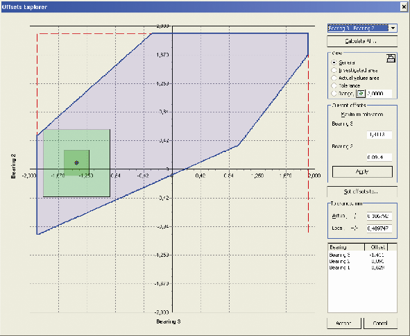
Fig. 1 Offset explorer window
deviations, both positive and negative, from the calculated bearing offsets that do not result in acceptance criteria violation. Allowable offsets hyperspace can be explored with a special Offset Explorer function using two dimensional sections, Fig. 1.
A calculation of the bush pressure distribution for non rotating shafts at alignment time defines the realistic position of the bearing reaction point and bearing bush stiffness by solving shaft-bush contact problems. The contact area and pressure diagrams give details of the bush-shaft engagement. A calculation of the hydrodynamic lubrication pressure for rotating shafts gives the possibility to estimate the position of the bearing reaction point in operation, evaluate film thickness and other bearing lubrication parameters resulted from the used shaft alignment design.
In executing shaft alignment procedures on board, it is important to know the permissible ranges of the measured parameters. Calculation of these ranges is based on the safe alignment tolerance amount.
Shaft alignment application can be used at the all stages of the ship’s life cycle: at the design phase, during construction and for the ship under repairing. At the two last stages reverse calculation functions are very useful.
Reverse calculations are direct alignment calculations fulfilled using bearing offsets automatically calculated from specific measured data, such as sags and gaps, bending stress, jack loads and shaft deflections. These calculations are indispensable for aligning propulsion shafts in ship repair projects.
The strain gauge alignment function is intended for onboard application, the associated calculation defining the bearing adjustments leading to the specified offsets. Measured bending stress or strain instrumentation readings are inputted to calculate the bearing adjustments, Fig. 2.
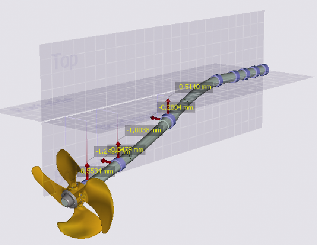
Fig. 2 Bearing adjustments diagram
Hydrodynamic loads onto propeller and hull deflections are of great importance for shaft alignment. Thereby special auxiliary modules to calculate constant and fluctuating hydrodynamic loads onto propeller and evaluate bearing displacements caused by hull deflection are provided.
2. SHAFT VIBRATION APPLICATIONS
The software calculates free vibration characteristics as well as steady forced vibration parameters in a frequency domain. The forced vibration calculation results for a single node or element may be presented in time domain form too.
The main results of a free vibration calculation for each type of vibration are as follows: natural frequencies and mode shapes as well as resonance speeds in the form of Campbell diagram and resonance table. Whirling vibration calculation results include the list of critical speeds for forward and backward whirling. Campbell diagram view for whirling vibration is shown in Fig. 3.
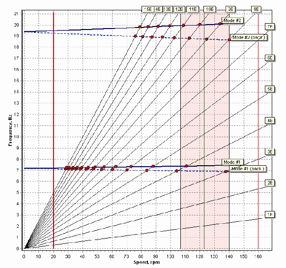
Fig 3 Whirling vibration Campbell diagram
Torsional vibration calculations may be performed for a complete propulsion train or its parts, with different states of clutch connections. Torsional vibration application additionally includes special graphics editor to create a mass-elastic system when the base model is not available, Fig. 4.
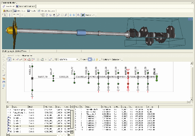
Fig. 4 Torsional vibration graphics editor
The software allows the automatically generated parts of such a mass-elastic system to be combined with the mass-elastic systems supplied by engine, gearbox and other rotating machinery manufacturers.
Forced vibration calculation can be performed for most dangerous type of vibration: torsional, axial and coupled axial-torsional. The last is available for directly driven installation only.
To calculate forced vibration two different methods are used: mode superposition method and full solution method. It is well known that one of the main problem of forced vibration calculation is to assign excitation and damping in propulsion train elements. A lot of possibilities to set excitation and damping parameters is one of the software advantages that make it flexible and easy to use.
If the propulsion train is diesel engine driven the calculations can be fulfilled for normal operation of the engine as well as for misfiring mode.
To explore forced vibration calculation results special interactive browser is provided. Vibration amplitudes, dynamical forces and stress dependence on shaft rotation speed can be seen in a graphic form. User has the possibility to select separate graphs to be included in calculation report.
The vibration calculation results are compared with the acceptance criteria.
3. CONCLUSIONS
The new CAE package for propulsion train calculation is a result of close cooperation of the Intellectual Maritime Technologies and Machine Support BV companies having of many years experience in propulsion shafting domain. Thanks to the software’s capabilities to perform reversed calculations, the theory and practical findings were cross-validated and guarantee accurate results.
In the development of new software for propulsion train calculations there was a continuous coordination with classification societies and leading OEMs of various components of the propulsion train, in order to meet their needs.
Concepts embodied in the developed system and object-oriented methodology enable further continual improvement in the software. It form a reliable basis to attain the final goal of propulsion shafting design to couple shaft alignment parameters with the vibration characteristics of propulsion shafting.
There are several directions for the future developments, including a full-featured Computer Aided Design (CAD) system for propulsion shafting design.
As a first step the possibility to import propulsion train 3D models created with the widely used mechanical CAD systems should be provided.
Special rule-based software for the shafting automatic synthesis can be developed as an aid for the shaft designers at the early stage of propulsion train design.
To top it all a condition monitoring system for propulsion train can be developed on the base of the presented software.