Yuriy A. Batrak*1, Anatoliy M. Serdjuchenko2 and Alexander I. Tarasenko2
1 Intellectual Maritime Technologies,
19-g/12 Krylova str., Mykolayiv 54038, Ukraine
2National University of Shipbuilding
9, Geroyiv Stalingrada av. Mykolayiv 54025, Ukraine
yuriy.batrak@gmail.com (e-mail address of lead author)
Abstract
Polar ships and other ice-class ships intended for navigation in ice-infested waters suffer from the transient torsional vibration induced by ice impacts on the propeller. Calculations of transient torsional vibration induced by ice impacts became mandatory since January 2011. In this paper the ShaftDesigner software approach for calculation of transient torsional vibration responses caused by ice impacts is discussed including an effective method for integration of differential equations of shaft motion. Results of detailed simulation of the propulsion plant installation dynamics are presented.
INTRODUCTION
The international economy and exploitation of natural resources of Northern areas requires elongating of shipping period in Arctic region and in Baltic Sea. That is the reason why numerous investigation projects were undertaken in the Northern countries last decades. New Rules for the ships navigating in ice that came into force in January 2011 include the requirements for calculation of transient torsional vibration, caused by ice impacts on the propeller blades.
Torsional vibration problems of the propulsion shafting are known more than a century. A lot of the theoretical studies and full scale measurements have been performed during this period. As a result classical propulsion shafting steady-state torsional vibration calculations (STVC), based on frequency domain calculations, guarantee safe operation of the ships in open water. The approximations of ice torque were developed based on the Finnish-Swedish rules [6] and adopted by all Classification Societies as a statutory. Design ice torque distributions designated as “Case 1”, “Case 2” and “Case 3” for 4-bladed propeller are depicted in Fig.1 depending on propeller rotation angle.
The approximations are very specific so time-domain approach looks most reasonable to apply for transient torsional vibration calculations (TTVC). In addition it enables simulation of propulsion plant dynamics on the whole.
Figure 1 – Ice induced torque graphs
ICE INDUCED ttvc IN SHAFTDESIGNER SOFTWARE
ShaftDesigner software is a multiproject, multi-state, FEM-based propulsion train software which seamlessly integrates all types of shaft engineering applications in one CAE package [1]. It provides shaft alignment design, axial, whirling and torsional vibration calculations using a single base model. TTVC induced by ice impacts is a special option of ShaftDesigner TVC. Samples of the propulsion shafting model and automatically generated mass-elastic system for the Chinese research ship Xue Long or “Snow Dragon” (ship that provided a rescue operation of Russian ship “Akademik Shokalskiy” in the Antarctic in the winter of 2014) are depicted in the Fig.2 and Fig.3.
Classical methods of numeric integration of the system of differential equations in the case of ice induced TTVC are inefficient and take a lot of time. There are strong recommendations to simplify a shaft model into a minimum lumped mass up to presentation of the engine by a single mass [4].
Simplifying procedure includes selection of the equivalent stiffness and recalculation of the damping. It is not a trivial procedure and requires certain skills and experience. After the engine masses are added together to one mass, the relative damping cannot be modelled at all. As a result the propulsion system dynamic properties are not quite adequately modelled that had been confirmed by the full scale measurements [3]. After simplification user must maintain two different models for the same project: one for STVC and one for TTVC. Undoubtedly this is not convenient in a shaft design process. It is why great efforts have been applied by the ShaftDesigner developers to avoid mass-elastic system simplification. The issues of a computational method selection are discussed hereafter.
Figure 2 – Propulsion shafting model of “Snow Dragon” ship
Figure 3 – Mass-elastic system of “Snow Dragon” propulsion shafting
There are some uncertainties in TTVC induced by ice impacts [4].
- During the ice blocks milling process the effective propeller inertia increased significantly, but due to lack of knowledge it is proposed to keep the inertia as for open water operation.
- It is uncertain if higher Archer coefficients than 20 are justified for propeller damping in the context of ice interaction, and thus it is advised to keep to 20. Currently it is unknown how the propeller damping works when in contact with ice blocks.
- Ice milling process takes 1-2 second when engine speed drop occurs. But considering the ice induced torque as a statutory Classification Societies Rules do not require changing its magnitude in connection with the speed drop.
- During the speed drop propeller for the short period operates in transient conditions so it is not quite correct to calculate propeller hydrodynamic moment as per steady conditions [7].
- During ice induced vibrations the most correct approach is to use the dynamic stiffness of the couplings for the fast component and the static stiffness for the slow component of a shaft vibration. In a general case of TTVC it is impossible so it is advised to calculate with the static stiffness only.
There are attempts to model propulsion system behaviour in all details. In general, this approach is commendable but using mass-elastic system simplification, statutory approximations of ice induce torque and above mentioned uncertainties question the idea to make TTVC as exact as possible using the simulation of propulsion system dynamics on the whole.
Taking into account above, Shaftdesigner TTVC module is organized strictly in accordance with the requirements of the Rules. All three required Cases of the statutory ice torque distributions are calculated simultaneously. Maximum of the torque resulting from ice/propeller interaction every time is equal to the design torque \({{Q}_{{max}}}\). Hydrodynamic propeller load is taken as per bollard conditions. For each shaft element the software searches for the worst result automatically both on torque Case and the Phase angle between the start of ice impacts and first engine crank position.
Full scale measurements [3] revealed great discrepancy of the measured and simulated engine speed drop. Therefore ShaftDesigner software provides parametric scaling of the engine speed drop.
Due to engine speed governor reaction on the ice induced speed drop fuel supply and mean indicating pressure increase. ShaftDesigner gives the possibility to evaluate the influence of mean indicating pressure rise.
Sample of calculation result for “Snow Dragon” ship at 111 rpm is depicted in Fig.4. Full model enables the vibration analysis in all elements.
Figure 4 – Torque in the propeller shaft
Dynamic properties of some flexible couplings may depend on the vibration frequency. Therefore couplings characteristics determination issue arises when time domain approach is used. In the case of linear system the major frequency of ice torque fast varying component spectra may be used for flexible coupling properties determination. This frequency in Hz can be estimated by the formulasas: \({{f}_{1}}=0,067n\) for the Case1 and \({{f}_{{2,3}}}=0,133n\) for the Cases 2 and 3, where \(n\) – propeller rotational speed, rpm.
NUMERICAL METHOD for ICE INDUCED TTVC
In quite general formulation ice induced transient torsion vibration problem must include parametric, time-dependent and nonlinear phenomena and therefore some elements of the matrices may include dependences on time t, angular vector \(\vec{\!\!\theta\!\!}\) and velocity vector \(\overrightarrow{{\dot{\theta}}}\). The complete mechanical form of the governing equations:
\(\mathbf{M}\overrightarrow{{\overset{\ddot{\ }}{\mathop{\!\!\theta\!\!}}\,}}+\mathbf{C}\overrightarrow{{\dot{\!\!\theta\!\!}}}+\mathbf{K}\text{ }\vec{\!\!\theta\!\!}=\vec{T}\left( t \right),\)where matrices \(\mathbf{M}\left( {t,\overrightarrow{{\!\!\theta\!\!}},\overrightarrow{{\dot{\!\!\theta\!\!}}}} \right),\text{ } \mathbf{C}\left( {t,\overrightarrow{{\!\!\theta\!\!}},\overrightarrow{{\dot{\!\!\theta\!\!}}}} \right),\text{ } \mathbf{K}\left( {t,\overrightarrow{{\!\!\theta\!\!}},\overrightarrow{{\dot{\!\!\theta\!\!}}}} \right),\text{ }\) are generalized inertia, damping and rigidity matrices of the vibration system respectively and \(\vec{T}\left( {t,\overrightarrow{{\!\!\theta\!\!}},\overrightarrow{{\dot{\!\!\theta\!\!}}}} \right)\) is a vector of generalized excitation moments.
ShaftDesigner software uses generalized Kujawski&Gallager algorithm of numeric integration of torsional vibration equations presented in mechanical form. It is very effective so it does not require any simplification of the mass-elastic system.
According to the fundamental publication [5] the majority of the numerical algorithms may be collected into three families – multistage techniques, multistep techniques and optimization techniques. The disadvantages of the multistage techniques (like Runge-Cutta method and Newmark β-method) are that some amount of the additional calculations for every temporal point \({{t}_{{k+1}}}\) must be carried out to achieve the required accuracy. The disadvantages of the multistep techniques (like Adams family algorithms) are that the algorithms could start only from some temporal point\(~{{t}_{{s+1}}},~s>1\) and therefore another algorithm has to be applied for the calculations on the starting interval \([{{t}_{0}},{{t}_{s}}]\). The disadvantages of the optimization techniques (like least-square family algorithms) related with the adequate formulation of the functional and minimization procedure for the specified problem.
Special testing of all above mentioned algorithms on different equations revealed that generalized Kujawski&Gallager optimization algorithm in general shows better results in accuracy and stability of the numerical results in comparison to the other algorithms.
The main ideas of the generalized Kujawski&Gallager algorithm are based on the polynomial approximation of the solution and excitation moments on the calculation interval. The errors generated by the approximation is minimized using the functional associated with the problem and formulated as weighted total square of the error, evaluated in some specified collocation point. The unknown value of angular vector would be derived from a minimization procedure, which finally results in the explicit numerical algorithm. More detailed description of generalized Kujawski&Gallager algorithm can be found in [2], [8].
SIMULATION OF PROPULSION PLANT DYNAMICS
Simulation is the imitation of the system response over time. The simulation requires that a model correctly represents the behaviour of the simulated system. Correct transient torsional vibration calculation is needed to be based on adequate simulation of propulsion plant dynamics. It is senseless to calculate propulsion shafting torsional vibration when the propulsion plant cannot operate safely under specified conditions.
To investigate the processes that may have taken place during propeller/ice interaction special software module was developed to simulate propulsion plant dynamics of modern commercial ship equipped with CPP, Fig. 5. For the simulation details see [2].
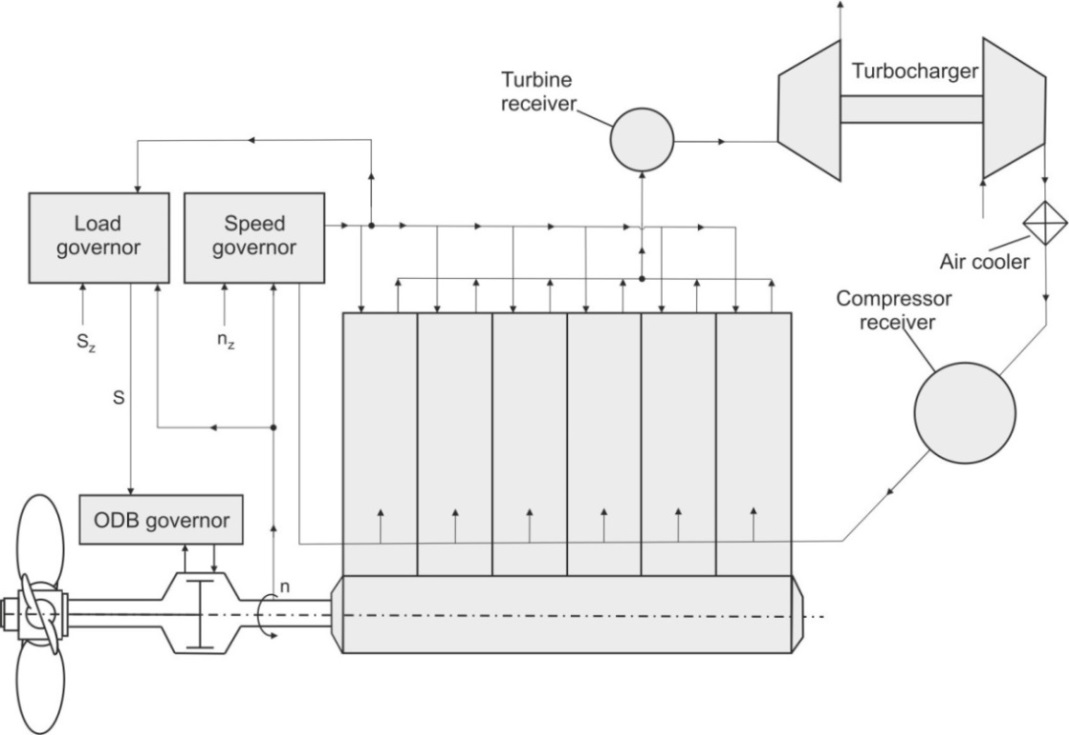
Figure 5 – Propulsion plant principal scheme
Engine, engine speed governor, turbine receiver, turbocharger, and compressor receiver are integrated into a single system. The indicating pressure diagram is recalculated every time depending on the fuel supply rate.

Figure 6 – “Snow Dragon” propulsion plant dynamics parameters
Using developed software propulsion plant dynamics of “Snow Dragon” ship, Fig. 2, was simulated. It was assumed that load governor sets CPP pitch
to provide 80% MCR at the nominal engine speed 111 rpm, maximum fuel supply is set as 1,1 of the nominal fuel supply. The simulation results for the Case 2 are depicted in Fig. 6. The following nine parameters are plotted:
- Mean Indicating pressure
- Propeller Torque
- Engine speed
- Exhaust gas temperature, °K
- Air-fuel ratio
- Turbocharger speed
- Turbine receiver temperature, °K
- Compressor receiver pressure, bar
- Turbine receiver pressure, bar
Dimensionless parameters are defined relative to their nominal values. The saw tooth line at the bottom shows the propeller revolutions
Using the simulation results it is possible to analyse the operation characteristics of the propulsion plant in the proposed conditions and make a decision concerning of their acceptability. For example for “Snow Dragon” ship conditions we found increased temperature of the exhaust valve and insufficient air-flow ratio at 21th second.
Among other restrictions on the propulsion plant operation compressor over pressure should be mentioned. Compressor receiver over pressure may result in dangerous turbocharger surging and cylinder safety valve opening.
Such detailed studies must be conducted for different installations, including that of four stroke engines to have more clear understanding of propulsion plant operation during the ice milling process and to elaborate more distinct Classification Rules requirements for TTVC induced by ice impacts.
SUMMARY
- ShaftDesigner software is a convenient tool for calculation of ice induced response. It estimates peak-to-peak and maximum torques for all shaft elements and for all statutory Cases of ice torque simultaneously. It does not require a special knowledge for propulsion plant simulation.
- Generalized Kujawski&Gallager algorithm of numeric integration of torsional vibration equations excludes simplification of mass-elastic system to have acceptable calculation time.
- Detailed simulations of different propulsion plants must be conducted to have a more clear understanding of propulsion plant operation during ice milling process and to elaborate more distinct Classification Rules requirements for TTVC induced by ice impacts.
- Taking into account the statutory character of the ice torque presented in Classification Societies Rules some simple TTVC principle should be developed. It is senseless to spend a lot of efforts to calculate the internal forces using the most accurate methods when the external loads and acceptance criteria are statutory and use high values for safety factors.
Slightly more accurate results cannot acquit the time and money necessary for full simulation of the power plant process during propulsion shafting design.