INDIAN-REGISTER-OF-SHIPPING.pdf (520 downloads)
RULES AND REGULATIONS FOR THE CONSTRUCTION AND CLASSIFICATION OF STEEL SHIPS, July 2015
ALIGNMENT
Pt 4 Ch 4 Sec 6
6.16 Stern tube and bearings
6.16.1 The length of the bearing in the sternbush next to and supporting the propeller is to be as follows:
a) For water lubricated bearings which are lined with lignum vitae, rubber composition or staves of approved plastic material; the length is to be not less than 4 times the diameter required for the tailshaft under the liner;
b) For bearings which are white-metal lined, oil lubricated and provided with an approved type of oil sealing gland;
i. the length of the bearing is to be not less than twice the diameter required for the tailshaft.
ii. the length of the bearing may be less provided the nominal bearing pressure will not exceed 0.8 [N/mm2] as determined by static bearing reaction calculation taking into account shaft and propeller weight which is deemed to be exerted solely on the aft bearing divided by the projected area of the shaft. However, the length of the bearing is to be not less than 1.5 times its actual diameter;
b) For bearings of cast iron, bronze which are oil lubricated and fitted with an approved oil sealing gland; the length of the bearing is, in general, to be not less than 4 times the diameter required for tailshaft;
c) For bearings which are grease lubricated, the length of bearing is to be not less than 4 times the diameter required for the tailshaft;
d) For water lubricated bearings lined with two or more circumferentially spaced sectors of an approved plastics material, in which it can be shown that the sectors operate on hydrodynamic principles, the length of the bearing is to be such that the nominal bearing pressure will not exceed 0.55 [N/mm2]. The length of the bearing is not to be less than twice its diameter;
e) For approved oil lubricated bearings of synthetic rubber, reinforced resin or plastic materials, the length of the bearing is to be not less than 2.0 times the rule diameter of the shaft in way of the bearing. The length of the bearing may be reduced provided the nominal pressure is not more than 6 bar as determined by static bearing reaction calculation taking into account shaft and propeller weight which is deemed to be exerted solely on the aft bearing divided by the projected area of the shaft. In any case
the length is not to be less than 1.5 times the actual diameter. Where the material has proven satisfactory testing and operating experience, consideration may be given to an increased bearing pressure.
Pt 4 Ch 4 Sec 8
8.7 Shaft alignment
8.7.1 For main propulsion installations, the shafting is to be aligned to give reasonable bearing reactions, and bending moments, taking into consideration following factors :
– Forces which may affect the reliability of the propulsion shafting system including weight of the propeller and shafts,
– Hydrodynamic forces acting on the propeller,
– Number of propeller blades in relation to diesel engine cylinders,
– Misalignment forces,
– Thermal expansion,
– Flexibility of engine and thrust bearing foundations,
– Engine induced vibrations, gear tooth loadings, flexible couplings,
– Effect of power take-off,
– Effect of hull deformations at all conditions of ship loading and operation.
Consideration is also to be given to any limits of vibrations and loadings specified by the equipment manufacturer. The Shipbuilder is to position the bearings and construct the bearing seatings to minimize the effects of movements under all operating conditions.
8.7.2 For geared installations, where two or more pinions are driving the final reduction wheel, calculations are to be submitted to verify that shaft alignment is such that proper bearing reactions are maintained under all operating conditions.
8.7.3 Shaft alignment calculations are to be submitted for the following alignment-sensitive types of installations for review:
i) Propulsion shafting with power takeoff or with booster power arrangements.
ii) Propulsion shafting for which the tail shaft bearings are to be slope bored.
iii) Propulsion shaft having diameter 300mm. and above in way of after most stern tube bearing
iv) Propulsion shafting arrangement requiring long shaft line.
The alignment calculations are to include bearing reactions, shear forces and bending moments along the shafting.
The alignment calculations are to be performed for the following conditions, as applicable:
– Theoretically aligned cold and hot conditions of the shaft with specified alignment tolerances.
– Deviation from the theoretical aligned conditions due to the forces exerted by power take-off or booster power.
Calculations are to be performed for the maximum allowable alignment tolerances and are to show that:
– Bearing loads under all operating conditions are within the acceptable limits specified by the bearing manufacturer.
– Bearing reactions are always positive (i.e. supporting the shaft).
– Shear forces and bending moments on the shaft are within acceptable limits in association with other stresses in the shaft.
– Forces and moments on propulsion equipment are within the limits specified by the machinery manufacturers.
8.7.4 Shaft alignment is to be verified by measurement.
TORSIONAL VIBRATION
Pt 4 Ch 4 Sec 8
8.1 Scope
8.1.1 The requirements of this Section are applicable to the following systems:
a) Main oil engine propulsion systems, except in the case of ships classed for smooth water service, when fitted with engines having powers less than 200 [kW].
b) Auxiliary oil engine machinery systems used for essential services, where the power developed by auxiliary engines is 200 [kW] and over.
c) Main propulsion systems formed by turbines or electric motors geared to the shafting and situated aft.
8.1.2 Unless otherwise advised, it is the responsibility of the Shipbuilder as the main contractor to ensure, in co-operation with the Engine builders, that the information required by this Section is prepared and submitted.
8.2 Basic system requirements
8.2.1 The systems are to be free from excessive torsional, axial and lateral vibration, and are to be aligned in accordance with tolerances agreed with the respective manufacturers.
8.2.2 Where changes are subsequently made to a dynamic system which has been approved, revised calculations are to be submitted for consideration.
8.4 Torsional vibration
8.4.1 General
8.4.1.1 Torsional vibration calculations, including an analysis of the vibratory torques and stresses for the dynamic systems formed by the oil engines, turbines, motors, generators, flexible couplings, gearing, shafting and propeller, where applicable, including all branches, are to be submitted for approval together with the associated plans.
8.4.1.2 Particulars of the division of power developed throughout the speed range for turbines or from all intended combinations of operation in oil engine installations having more than one engine and/or with power take-off systems are to be submitted.
8.4.1.3 Any special speed requirements for prolonged periods in service are to be indicated, e.g., range of trawling revolutions per minute, range of operation revolutions per minute with a controllable pitch propeller, idling speed, etc.
8.4.1.4 The calculations and/or measurements carried out on oil engine installations containing transmission items sensitive to vibratory torque, e.g. gearing, flexible couplings, or generator rotors and their drives, are to take into account the effects of engine malfunction commonly experienced in service, such as cylinder(s) not firing.
8.4.1.5 Restricted speed ranges will be imposed in regions of speed where stresses are considered to be excessive for continuous running. Similar restrictions will be imposed, or other protective measures required to be taken, where vibratory torques are considered to be excessive for particular machinery items.
8.4.1.6 Where calculations indicate the possibility of excessive torsional vibration within the range of working speeds, torsional vibration measurements, using the appropriate recognized techniques, may be required to be taken from the machinery installation for the purpose of determining the need for restricted
speed ranges.
8.4.2 Permissible limits of stresses due to torsional vibrations
8.4.2.1 Alternating torsional vibration stresses are stresses resulting from the alternating torque which is superimposed on the mean torque.
8.4.2.2 In no part of the propulsion system may the alternating torsional vibration stresses exceed the values of 1 for continuous operationand 2 for transient running.
8.4.2.3 For continuous operation the permissible stresses due to alternating torsional vibrations are not to exceed the following values:
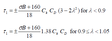
where,
1 = permissible stress due to torsional vibrations for continuous operation [N/mm2];
σB = tensile strength of shaft material [N/mm2];
For calculation purposes, this value is not to be taken greater than:
• 600 [N/mm2] for carbon and carbon manganese steels; and
• 800 [N/mm2] for alloy steels;
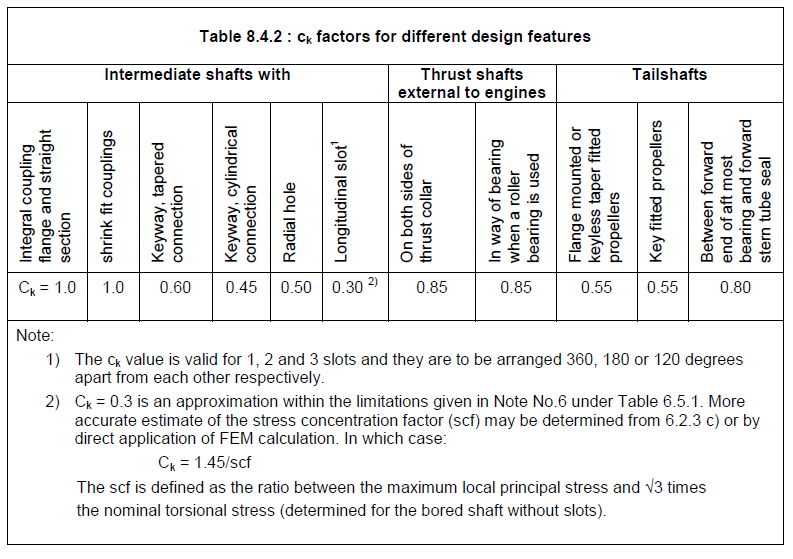
Ck = factor for different shaft design features as given in Table 8.4.2;
CD = size factor = 0.35 + 0.93d-0.2;
do = shaft outside diameter under consideration [mm];
λ = speed ratio = n/no;
n = speed in rpm under consideration at rated power;
no = rated speed in rpm.
8.4.2.4 Where a vessel, because of its type of employment, is operated predominantly in the lower speed range, special consideration may be given to the permissible stresses for continuous operation.
8.4.2.5 Where the stresses exceed the limiting values of τ1 for continuous operation, restricted speed ranges are to be imposed which are only allowed to be passed through rapidly.
8.4.2.6 Restricted speed ranges are not acceptable, in the speed range between 0.8 to 1.05 of the rated speed. The limits of the barred speed range are to be calculated in accordance with the following formula unless proved to be otherwise.
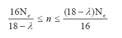
where,
nc = critical speed in [rpm].
8.4.2.7 For transient running the permissible stresses due to the alternating torsional vibrations are not, in any case, to exceed the values given by the following formula:
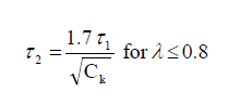
where,
2 = permissible stress due to torsional vibrations for transient running.
AXIAL VIBRATION
Pt 4 Ch 4 Sec 8
8.5.1 For all main propulsion shafting systems, the Shipbuilders are to ensure that amplitudes due to axial vibrations are satisfactory throughout the speed range, so far as practicable. Where appropriate, amplitudes may be reduced by the use of suitable vibration dampers or phasing of propeller and engine, etc.
8.5.2 Unless previous experience of similar installation shows it to be unnecessary, calculations of the shafting system are to be carried out. These calculations are to include the effect of the thrust block seating and the surrounding hull structure taking part in the vibration. The result of these calculations or the evidence of previous experience is to be submitted for consideration.
8.5.3 Where calculations indicate the possibility of excessive axial vibration amplitudes within the range of working speeds, measurements using an appropriate recognized technique may be required to be taken from the shafting systems for the purpose of determining the need for restricted speed ranges.
LATERAL VIBRATION
Pt 4 Ch 4 Sec 8
8.6 Lateral vibrations
8.6.1 For all main propulsion shafting systems, the Shipbuilders are to ensure that amplitudes due to lateral vibrations are satisfactory throughout the speed range.
8.6.2 Unless previous experience of similar installations shows it to be unnecessary, calculations of lateral, or bending, vibration characteristics of the shafting system are to be carried out. These calculations, taking account of dynamic bearing stiffnesses, are to cover the frequencies giving rise to all critical speeds which may result in significant amplitudes within the speed range, and are to indicate relative deflections and bending moments throughout the shafting system.
8.6.3 The results of these calculations, or the evidence of previous experience, is to be submitted for consideration.
8.6.4 Where calculations indicate the possibility of excessive lateral vibration amplitudes within the range of working speeds, measurements using an appropriate recognized technique may be required to be taken from the shafting system for the purpose of determining the need for restricted speed ranges.