DOUBLE BOTTOM DEFLECTIONS INDUCED BY SOLAR HEAT IN THE DRY DOCK AND AFLOAT
Dr.Yuriy Batrak,
Mykola Lavrov
All shaft alignment guides contain the requirement to undertake shaft alignment early in the morning or when it is cloudy. This requirement is introduced to avoid the significant effect of solar heat on shafting or engine alignment. This paper presents the field measurements of double bottom deflections induced by solar heat within the engine rooms of two tankers. Double bottom deflections were measured in the dry dock and in the waterborne conditions. Measured data are compared with the calculated values.
The practice of equipment installation has proved that deformations of the ship hull structures caused by solar heat are one of the significant factors influencing the alignment of the main engine and propulsion shafting both in a dry dock and in waterborne conditions.
To estimate the level of double bottom deflections connected with sun heat the field measurements were conducted on two tankers equipped with two-stroke diesel engines and having aft engine room layout. The first ship (length overall 178,5 m) was in the dry dock (measurements No. 1) and the second ship (length overall 179,0 m) was afloat (measurements No. 2). The ships are of the same projects but had minor differences in design. Both studies were undertaken at the summertime.
During measurements No.1 the ship hull was supported by ship carrier bogies equipped with hydraulic jacks, Fig. 1.
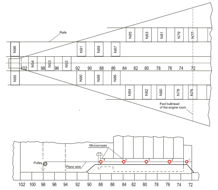
Fig. 1 Arrangement of the ship carrier bogies and measurement equipment
The pistons of the carrier bogies located forward from the engine room were blocked by lock nuts and used as ordinary supports, while the aft hull part was supported by hydraulic jacks with specially set pressures. To exclude the effect of the factors not related to the thermal deflections, the hydraulic jacks pressures were reset twice.
The following parameters were measured:
- Air and deck double bottom structures temperature.
The air temperature and the temperature difference between the boat deck and the bottom for the portside (PS) and the starboard (SB) are shown in Fig. 2. The accuracy of temperature measurements is ±1 °С. The maximum difference of the deck and bottom structures temperature is about 18°C.
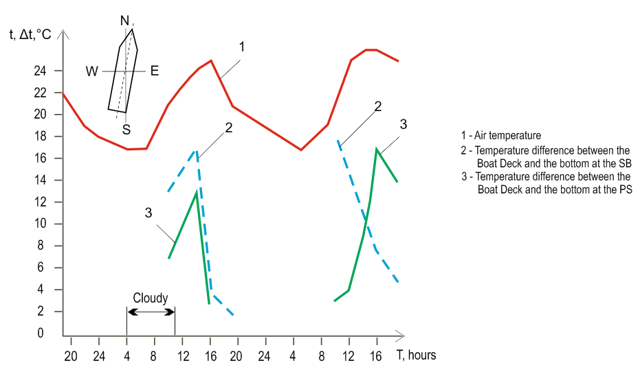
Fig. 2 Change of the air temperature and the temperature difference between the Boat Deck and the bottom for the PS and the SB for two days.
Pressure in the carrier bogies hydraulics system.
The pressure was measured by the pressure gauges with the accuracy of ±0,25MPa. Pressure of
22,0 MPa corresponds to the rated load of 1500 kN.
- Relative double bottom deflections.
The double bottom deflections in the vertical plane were measured using МPB-2 type measuring microscopes having the accuracy of ±0,01 mm and a piano wire of 0,3 mm diameter (see Fig. 1). The piano wire was tensioned over the engine foundation top plate on the SB side. One end of the wire was fixed on the engine room forward bulkhead; the movable end was attached to the web frame by means of the pulley, in the immediate vicinity of the aft peak bulkhead. The weight hanged on the movable piano wire end ensured constant tension of the wire. Magnetic brackets with measuring microscopes were installed at five positions. The length of the engine room is 23,4 m, the length of the piano wire is 20,8 m.
The results of the DB deflections measurement are shown in Table 1.
Table 1. DOUBLE BOTTOM DEFLECTIONS IN THE DRY DOCK
| Measurement time, hours | Relative deflections at the measurement points, mm | ||||
| #1 | #2 | #3 | #4 | #5 | |
| 20:00 | 0,02 | 0,02 | 0,03 | 0,00 | 0,02 |
| 22:00 | 0,00 | 0,00 | 0,00 | 0,00 | 0,00 |
| 24:00 | -0,01 | -0,01 | -0,02 | -0,01 | -0,03 |
| 4:00 | -0,03 | -0,05 | -0,07 | -0,05 | -0,08 |
| 7:00 | -0,03 | -0,05 | -0,07 | -0,05 | -0,08 |
| 10:00 | -0,01 | 0,00 | -0,03 | -0,01 | -0,03 |
| 14:00 | 0,02 | 0,05 | 0,05 | 0,19 | 0,22 |
| 16:00 | 0,02 | 0,08 | 0,10 | 0,21 | 0,25 |
| 19:00 | -0,04 | -0,05 | -0,05 | 0,02 | 0,08 |
| 24:00 | -0,06 | -0,08 | -0Д1 | -0,01 | -0,01 |
| 5:00 | -0,07 | -0,10 | -0,12 | -0,05 | -0,07 |
| 9:00 | -0,05 | -0,05 | 0,03 | 0,00 | -0,04 |
| 11:00 | -0,05 | -0,01 | -0,09 | -0,11 | -0,13 |
| 12:00 | -0,03 | 0,04 | -0,03 | -0,03 | -0,01 |
| 14:00 | -0,01 | 0,07 | 0,05 | 0,05 | 0,08 |
| 16:00 | -0,01 | 0,05 | 0,02 | 0,05 | 0,09 |
| 19:00 | -0,08 | -0,08 | -0,16 | -0,17 | -0,13 |
The carrier bogies prevented general hull girder temperature deflections and as a result, the pressure in carrier bogies hydraulic systems and correspondent forces have been changed over time. The supporting forces resultant magnitude and its distance to ER forward bulkhead are depicted in Fig.3. To evaluate the measured deflections FEM model of the engine room double bottom structure in the beam approach was created. External loads which have been applied in the FEM model to the double bottom girders were calculated using the pressure in hydraulic jacks in each specified moment.
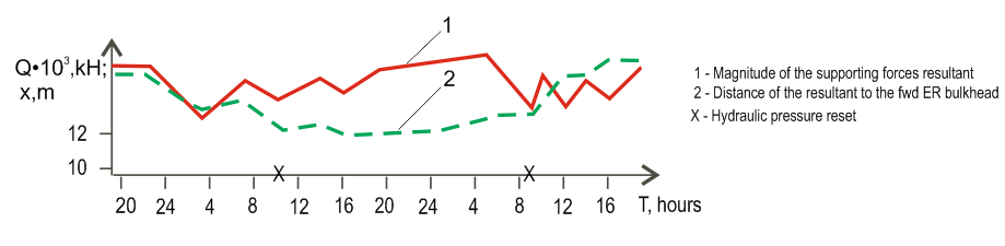
Fig. 3 Parameters of the Supporting forces resultant
Comparison of the calculated and measured double bottom deflections (Fig. 4) shows satisfactory agreement. Maximum peak-to-peak deflection at point #4 is 0,36 mm. The obtained result makes evident the fact that engine room double bottom deflections in a dry dock occur mainly due to the change of the supporting structure reactions caused by the hull girder general thermal deformation. Thus it is impossible to avoid not controlled machinery misalignment when the ship is in a dry dock.
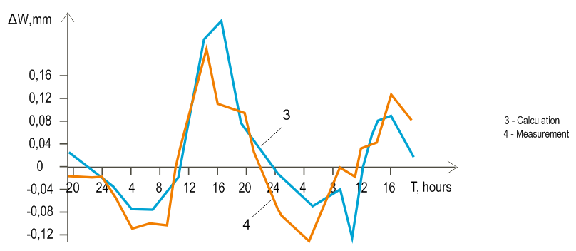
Fig. 4 Deflection in the middle of the engine room
In the Measurements #2, the ship was at the pier after launching. Ship draft at the F.P. was 3,8 m and at the A.P. 4,4 m. The ship did not take any cargo and ballast during measurements so all the deflections at the engine room area occur due to the temperature changes only. The following parameters were measured:
- Air temperature;
- Water temperature;
- Decks, platforms, and double bottom structures temperature;
- Double bottom deflections in the vertical plane.
The temperature change curves are shown in the Fig.5. The maximum difference of the deck and bottom structures temperature was 41,0°C. The outboard water temperature changed from 21,5 °С in the night time to 23,0 °С in the day time. The temperature of the hull remained almost constant, around 27,0°С. Only the Boat Deck parts of 4 m wide were exposed to sun heat.
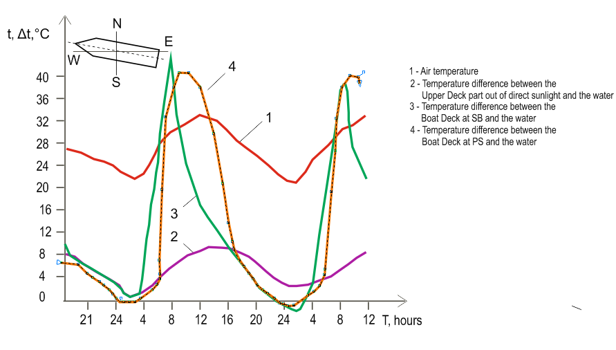
Fig. 5 Air temperature and the temperature difference between the hull structures and the water
The double bottom deflections were measured using measuring microscopes a piano wire stretched between fore and aft bulkheads of the engine room. The engine room length equal to the deflections measuring area is 24,2 m. Measurements results are shown in Fig. 6.
Double bottom deflections caused by temperature deformations were assessed theoretically. Taking into account that calculation purpose the moment of inertia of the cross-sectional area over the considered part of the hull length was taken to be constant and equal to the moment of inertia of the hull cross section at the middle of the engine room.
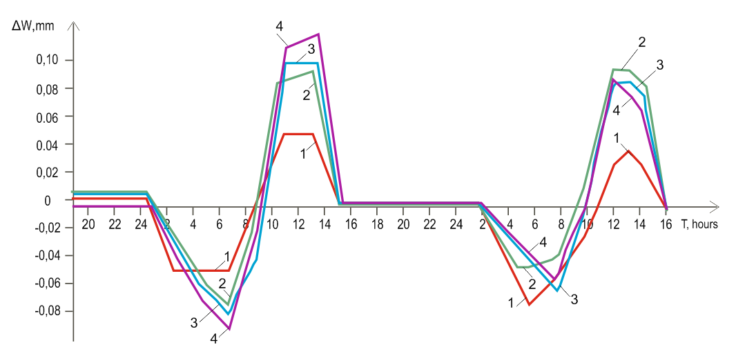
Fig. 6 Double bottom deflections within two days (microscopes Nos. 1-4)
The maximum relative pick-to-peak hull deflection in the middle of the engine room is calculated on the base of the Shimanski formula:
where:
µ – linear expansion coefficient, for steel;
l – length of the area under consideration (l=24,2 m);
– the total area of the hull girder deck part = 0,064m2)
– the maximum temperature difference mean value ( = 41 °С);
zk – a distance of the Boat Deck to the neutral axis (zk = 8 m);
– inertia moment of the cross section area ( = 77,84)
As a result of the calculation, W = 0,23 mm was obtained; the discrepancy with the range of experimental deflections does not exceed 10%.
On the base of the experimental studies and undertaken calculations, the following conclusions can be drawn.
CONCLUSIONS
1. Local deflections are the main component engine room double bottom deflections in a dry dock. The contribution of general hull girder thermal deformation in a dry dock is small because the supporting structures prevent general hull girder thermal deflections.
2. For the ship in a dry dock condition, the engine room local double bottom deflections occur continuously and mainly due to the changes of the support structure reactions caused by general hull girder thermal deformations.
3. It is impossible to predict and to avoid not controlled machinery misalignment when the ship is in a dry dock. The problem can be solved by introducing a buoyancy simulation technique using hydraulic jacks under the hull. The advantage of the simulation approach is the opportunity to take into account not only different loading conditions in operation but future thermal hull deflections.
4. When a ship is afloat engine and shafting bearings also have deviations from the initial positions due to solar heat. The thermal deflections are smaller than those in a dry dock but are quite enough to distort shafting and engine alignment.